ICA12-50JPLLB
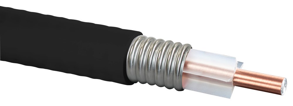
1/2" Plenum-Rated Aluminum Air-Dielectric Coaxial Cable, Black Color
Designed for Public Safety to Commercial 5G Applications
Rev : H | Rev date : 12 Jan 2026
ClearFill®Line 1/2" low-loss air dielectric cable, Plenum-rated, CMP
FEATURES / BENEFITS
- Supports Multiple RF Signals
- Complete Shielding
The solid outer conductor of the ClearFill®Line coaxial cable creates a continuous RFI/EMI shield that minimizes system interference.
- Outstanding Intermodulation Performance
RFS Technologies coaxial cable's solid inner and outer conductors virtually eliminate intermods. Intermodulation performance is also confirmed with state-of-the-art equipment at the RFS Technologies factory.
- Wide Range of Applications
Typical areas of application are feedlines for plenum-space installations within occupied buildings or structures.
Applications |
|---|
| Applications | | In Building | DAS |
|
Structure |
|---|
| Cable Type | | Air-Dielectric, Corrugated | | Size | | 1/2" | | Inner Conductor Diameter | mm (in) | 4.8 (0.19) | | Inner Conductor Material | | Copper-Clad Aluminum Wire | | Dielectric Diameter | mm (in) | 11.8 (0.464) | | Dielectric Material | | Extruded Polyethylene | | Outer Conductor Diameter | mm (in) | 13.8 (0.54) | | Outer Conductor Material | | Corrugated Aluminum | | Jacket Diameter | mm (in) | 15.93 (0.627) | | Jacket Material | | Flame Retardant PVC |
|
Testing and Environmental |
|---|
| Fire Performance | | CMP (Communications Multipurpose Plenum) | | Regulatory Compliance | | NFPA 262 (UL910) / CATVP / CMP / UL444 / Canadian CSA C.22.2/FT6 | | Installation Temperature | °C(°F) | -20 to 60 (-4 to 140) | | Storage Temperature | °C (°F) | -40 to 85 (-40 to 185) | | Operation Temperature | °C(°F) | -40 to 85 (-40 to 185) |
|
Electrical Specifications |
|---|
| Impedance | Ω | 50 +/- 1 | | Maximum Frequency | GHz | 6 | | Velocity | % | 88 | | Capacitance | pF/m (pF/ft) | 75 (22.86) | | Inductance | uH/m (uH/ft) | 0.19 (0.058) | | Peak Power Rating | kW | 40 | | RF Peak Voltage | Volts | 2000 | | Jacket Spark | Volt RMS | 8000 | | Inner Conductor dc Resistance | Ω/1000 m (Ω/1000 ft) | 1.48 (0.45) | | Outer Conductor dc Resistance | Ω/1000 m (Ω/1000 ft) | 2.29 (0.7) | | Return Loss (VSWR) Performance | | 24 (1.13) @ 698-960 MHz
24 (1.13) @ 1395-1432 MHz
24 (1.13) @ 1700-2155 MHz
20 (1.22) @ 2300-2700 MHz
18 (1.29) @ 3550-4200 MHz
18 (1.29) @ 5150-6000 MHz | | Temperature & Power | | High Power Rating |
|
Mechanical Specifications |
|---|
| Cable Weight, Nominal | kg/m (lb/ft) | 0.238 (0.16) | | Minimum Bending Radius, Single Bend | mm (in) | 76 (3) | | Minimum Bending Radius, Repeated Bends | mm (in) | 127 (5) | | Bending Moment | Nm (lb-ft) | 5.4 (4) | | Tensile Strength | N (lb) | 549 (150) | | Recommended / Maximum Clamp Spacing | m (ft) | 0.5 / 0.9 (1.8 / 3) | | Crush Strength | kg/mm (lb/ln) | 1.25 (70) |
|
Attenuation @ 20°C (68°F) and Power Rating @ 40°C (104°F) |
|---|
| Frequency, MHz | dB per 100m | dB per 100ft | Power, kW | | 0.5 | 0.16 | 0.05 | 40 | | 1 | 0.23 | 0.07 | 32.80 | | 1.5 | 0.29 | 0.09 | 26.80 | | 2 | 0.33 | 0.10 | 23.20 | | 10 | 0.74 | 0.23 | 10.30 | | 20 | 1.06 | 0.32 | 7.22 | | 30 | 1.30 | 0.40 | 5.89 | | 50 | 1.68 | 0.51 | 4.55 | | 88 | 2.25 | 0.69 | 3.40 | | 100 | 2.41 | 0.73 | 3.18 | | 108 | 2.51 | 0.76 | 3.05 | | 150 | 2.98 | 0.91 | 2.57 | | 174 | 3.22 | 0.98 | 2.38 | | 200 | 3.46 | 1.05 | 2.21 | | 300 | 4.29 | 1.31 | 1.79 | | 400 | 5 | 1.52 | 1.53 | | 450 | 5.32 | 1.62 | 1.44 | | 500 | 5.63 | 1.72 | 1.36 | | 512 | 5.71 | 1.74 | 1.34 | | 600 | 6.22 | 1.90 | 1.23 | | 700 | 6.76 | 2.06 | 1.14 | | 750 | 7.02 | 2.14 | 1.09 | | 800 | 7.28 | 2.22 | 1.06 | | 824 | 7.40 | 2.25 | 1.04 | | 894 | 7.74 | 2.36 | 0.99 | | 900 | 7.76 | 2.37 | 0.99 | | 925 | 7.88 | 2.40 | 0.98 | | 960 | 8.05 | 2.45 | 0.96 | | 1000 | 8.23 | 2.51 | 0.93 | | 1250 | 9.32 | 2.84 | 0.83 | | 1400 | 9.93 | 3.03 | 0.78 | | 1500 | 10.30 | 3.15 | 0.75 | | 1700 | 11.10 | 3.38 | 0.70 | | 1800 | 11.50 | 3.49 | 0.67 | | 2000 | 12.20 | 3.71 | 0.63 | | 2100 | 12.50 | 3.81 | 0.62 | | 2200 | 12.80 | 3.92 | 0.61 | | 2300 | 13.20 | 4.02 | 0.59 | | 2400 | 13.50 | 4.12 | 0.57 | | 2500 | 13.80 | 4.22 | 0.56 | | 2600 | 14.20 | 4.31 | 0.55 | | 2700 | 14.50 | 4.41 | 0.54 | | 3000 | 15.40 | 4.69 | 0.51 | | 3500 | 16.90 | 5.14 | 0.46 | | 3600 | 17.10 | 5.22 | 0.46 | | 4000 | 18.30 | 5.56 | 0.43 | | 4500 | 19.60 | 5.97 | 0.40 | | 5000 | 20.90 | 6.36 | 0.38 | | 5500 | 22.10 | 6.74 | 0.36 | | 6000 | 23.30 | 7.11 | 0.34 |
|