
- Home
- /
- LCF78-50JFNA-BAA
LCF78-50JFNA-BAA
7/8" CELLFLEX® Premium Attenuation Low-Loss Foam-Dielectric BAA Compliant Coaxial Cable
CELLFLEX®7/8" premium attenuation low loss flexible cable support CBRS, C-Band up to 4.2GHz; flame retardant/ halogen free jacket
FEATURES / BENEFITS
- BAA Compliant
RFS Technologies is proud to announce that the product of LCF78-50JFNA-BAA manufactured by RFS Technologies Meriden Factory in CT, U.S. is BAA compliant with Federal Transit Administration's requirements. - Ultra Low Attenuation
The further reduced attenuation of CELLFLEX® premium attenuation coaxial cable results in extremly efficient signal transfer in your RF system, especially at high frequencies. - Complete Shielding
The solid outer conductor of CELLFLEX® coaxial cable creates a continuous RFI/EMI shield that minimizes system interference. - Low VSWR
Special low VSWR versions of CELLFLEX® coaxial cables contribute to low system noise. - Outstanding Intermodulation Performance
CELLFLEX® coaxial cable's solid inner and outer conductors virtually eliminate intermods. Intermodulation performance is also confirmed with state-of-the-art equipment at the RFS Technologies factory. - High Power Rating
Due to their low attenuation, outstanding heat transfer properties and temperature stabilized dielectric materials, CELLFLEX® cable provides safe long term operating life at high transmit power levels. - Wide Range of Application
Typical areas of application are: feedlines for broadcast and terrestrial microwave antennas, wireless cellular, PCS and ESMR base stations, cabling of antenna arrays, and radio equipment interconnects. - Meets or Exceeds: IEC 60754-1, -2; IEC 60332-1-1, -2;IEC 61034-1, -2; IEC 60332-3-24 (formerly IEC 60332-3-C)
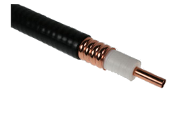
7/8" CELLFLEX® Low-Loss Foam Dielectric Coaxial Cable
Technical features
| ||||||||||||||||||
| ||||||||||||||||||||||||||||||||||||
| ||||||||||||||||||
| ||||||||||||||||||||||||||||||||||||||||||
| |||||||||||||||||||||
| ||||||||||||||||||||||||||||||||||||||||||||||||||||||||||||||||||||||||||||||||||||||||||||||||||||||||||||||||||||||||||||||||||||||||||||||||||||||||||||||||||||||||||||||||||||||||||||||||
External Document Links
Notes
Related Products

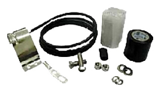
CEAR-78
Connector grounding kit
- Type of Grounding Kit : Connector grounding kit
- Package Quantity : 1
- Weight per piece, kg (lb) :
Grounding Kit
Connector grounding kit
Grounding terminal for AC-profile
High speed grounding kit for CELLFLEX® LCF 78
Connector grounding kit
Grounding Kit, Pre-formed Copper Strap, 1.5m (60") for CELLFLEX® 7/8" Cable
Connector grounding kit
Wall Feedthrough Sealing
Feed through assemblies for 7/8" coaxial cable, 102mm (4"), 1-entry
Feed through assemblies for 7/8" coaxial cable, 102mm (4"), 2-entries
Feed through assemblies for 7/8" coaxial cable, 102mm (4"), 3-entries
Feed through assemblies for 7/8" coaxial cable, 102mm (4"), 4-entries
Wall feed through (without feed through plate)
Tools
Stripping tool for high speed grounding kit GKSPEED-78 series
Hand tool kit for the installation of connectors and grounding kits on CELLFLEX® Cables
Hoisting Grip for Coaxial Cable and Elliptical Waveguide, Closed Lacing
Hoisting Grip for Coaxial Cable and Elliptical Waveguide, Lace-Up
Automated trimming tool, LCF78, UCF 78, OMNI FIT Premium, Trim Series D01
Flaring Tool LCF 7/8" for Universal Trimming Tools
Clamps
Double Multi-block hanger three layers, with angle member adapter
Double Multi-block hanger one layer, with angle member adapter
Single Multi-block hanger one layer, with angle member adapter
Single Multi-block hanger two layer, with angle member adapter
Single Multi-block hanger three layer, with angle member adapter
Cable hanger, non-insulated, bolt-on, for 7/8" coaxial cable and E100, E105 elliptical waveguide
Snap-In Hangers, 7/8", stainless steel (kit of 10)
Stackable Snap-In Hangers, 7/8", stainless steel (kit of 10)
Connectors
4.3-10 Female Connector for 1/2" Coaxial Cable, OMNI FIT™ standard, O-ring sealing
N Male Connector for 7/8" Coaxial Cable, OMNI FIT™ Premium,
Straight, O-Ring and compression sealing
N Female Connector for 7/8" Coaxial Cable, OMNI FIT™ Premium,
Straight, O-Ring and compression sealing
7-16 DIN Male Connector for 7/8" Coaxial Cable, OMNI FIT™ Premium,
Right Angle, O-Ring and compression sealing
7-16 DIN Male Connector for 7/8" Coaxial Cable, OMNI FIT™ Premium,
Straight, O-Ring and compression sealing
7-16 DIN Female Connector for 7/8" Coaxial Cable, OMNI FIT™ Premium, Straight, O-Ring and compression sealing
4.3-10 Male Straight Connector for 7/8" Coaxial Cable, OMNI FIT™ Premium, Polymer claw and compression sealing
4.3-10 Female Straight Connector for 7/8" Coaxial Cable, OMNI FIT™ Premium, Polymer claw and compression sealing
N Male Connector for 7/8" Coaxial Cable, OMNI FIT™ standard, O-ring sealing
7-16 DIN Female Connector for 7/8" Coaxial Cable, OMNI FIT™ standard, O-ring sealing
N Male Connector for 7/8" Coaxial Cable, OMNI FIT™ standard, O-ring sealing
N Female Connector for 7/8" Coaxial Cable, OMNI FIT™ standard, O-ring sealing
7-16 Male Connector for 7/8" Coaxial Cable, OMNI FIT™ standard, O-ring sealing
7-16 DIN Female Connector for 7/8" Coaxial Cable, OMNI FIT™ standard, O-ring sealing
4.3-10 Male Push-Pull Connector for 7/8" Coaxial Cable, OMNI FIT™ standard, O-ring sealing
4.3-10 Male Connector for 7/8" Coaxial Cable, OMNI FIT™ standard, O-ring sealing
4.3-10 Male Hand-Screw Connector for 7/8" Coaxial Cable, OMNI FIT™ standard, O-ring sealing
4.3-10 Female Connector for 7/8" Coaxial Cable, OMNI FIT™ standard, O-ring sealing
7-16 DIN Male Connector for 7/8" Coaxial Cable, OMNI FIT™ Premium,
Straight, O-Ring and compression sealing
7-16 DIN Female Connector for 7/8" Coaxial Cable, OMNI FIT™ Premium, Straight, O-Ring and compression sealing
4.3-10 Female Straight Connector for 7/8" Coaxial Cable, OMNI FIT™ Premium, O-Ring and compression sealing
4.3-10 Male Straight Connector for 7/8" Coaxial Cable, OMNI FIT™ Premium, O-Ring and compression sealing
N Male Connector for 7/8" Coaxial Cable, OMNI FIT™ Premium,
Straight, O-Ring and 360° compression sealing
N Female Connector for 7/8" Coaxial Cable, OMNI FIT™ Premium,
Straight, O-Ring and 360° compression sealing
Coaxial Transmission Line
7/8" CELLFLEX® Lite Low-Loss Foam-Dielectric Coaxial Cable
7/8" CELLFLEX® Premium Attenuation Low-Loss Foam-Dielectric Coaxial Cable
7/8" CELLFLEX® Lite Low-Loss Foam-Dielectric Coaxial Cable
7/8" CELLFLEX® Premium Attenuation Low-Loss Foam-Dielectric Coaxial Cable
7/8" CELLFLEX® Premium Attenuation Low-Loss Foam-Dielectric Coaxial Cable

BOOT4-78-1
Feed through assemblies for 7/8" coaxial cable, 102mm (4"), 1-entry
- Product Line : Coaxial Cable Accessories
- Transmission Line Type : LCF78, UCF78
- Cable Size : 7/8"
BOOT4-78-2
Feed through assemblies for 7/8" coaxial cable, 102mm (4"), 2-entries
- Product Line : Coaxial Cable Accessories
- Transmission Line Type : LCF78, UCF78
- Cable Size : 7/8"
BOOT4-78-3
Feed through assemblies for 7/8" coaxial cable, 102mm (4"), 3-entries
- Product Line : Coaxial Cable Accessories
- Transmission Line Type : LCF78, UCF78
- Cable Size : 7/8"
BOOT4-78-4
Feed through assemblies for 7/8" coaxial cable, 102mm (4"), 4-entries
- Product Line : Coaxial Cable Accessories
- Transmission Line Type : LCF78, UCF78
- Cable Size : 7/8"

JSTRIP-78-2
Stripping tool for high speed grounding kit GKSPEED-78 series
- Product Line : Coaxial Cable Accessories
- Product Type : Tool
- Cable Size : 7/8"
Tools Leaflet
Grounding Kit
Connector grounding kit
High speed grounding kit for CELLFLEX® LCF 78
Grounding Kit, Pre-formed Copper Strap, 1.5m (60") for CELLFLEX® 7/8" Cable
Wall Feedthrough Sealing
Feed through assemblies for 7/8" coaxial cable, 102mm (4"), 1-entry
Feed through assemblies for 7/8" coaxial cable, 102mm (4"), 2-entries
Feed through assemblies for 7/8" coaxial cable, 102mm (4"), 3-entries
Feed through assemblies for 7/8" coaxial cable, 102mm (4"), 4-entries
Wall feed through (without feed through plate)
Clamps
Double Multi-block hanger three layers, with angle member adapter
Double Multi-block hanger one layer, with angle member adapter
Single Multi-block hanger one layer, with angle member adapter
Single Multi-block hanger two layer, with angle member adapter
Single Multi-block hanger three layer, with angle member adapter
Cable hanger, non-insulated, bolt-on, for 7/8" coaxial cable and E100, E105 elliptical waveguide
Snap-In Hangers, 7/8", stainless steel (kit of 10)
Stackable Snap-In Hangers, 7/8", stainless steel (kit of 10)
Tools
Hand tool kit for the installation of connectors and grounding kits on CELLFLEX® Cables
Hoisting Grip for Coaxial Cable and Elliptical Waveguide, Closed Lacing
Hoisting Grip for Coaxial Cable and Elliptical Waveguide, Lace-Up
Automated trimming tool, LCF78, UCF 78, OMNI FIT Premium, Trim Series D01
Flaring Tool LCF 7/8" for Universal Trimming Tools
Connectors
4.3-10 Female Connector for 1/2" Coaxial Cable, OMNI FIT™ standard, O-ring sealing
N Male Connector for 7/8" Coaxial Cable, OMNI FIT™ Premium,
Straight, O-Ring and compression sealing
N Female Connector for 7/8" Coaxial Cable, OMNI FIT™ Premium,
Straight, O-Ring and compression sealing
7-16 DIN Male Connector for 7/8" Coaxial Cable, OMNI FIT™ Premium,
Right Angle, O-Ring and compression sealing
7-16 DIN Male Connector for 7/8" Coaxial Cable, OMNI FIT™ Premium,
Straight, O-Ring and compression sealing
7-16 DIN Female Connector for 7/8" Coaxial Cable, OMNI FIT™ Premium, Straight, O-Ring and compression sealing
4.3-10 Male Straight Connector for 7/8" Coaxial Cable, OMNI FIT™ Premium, Polymer claw and compression sealing
4.3-10 Female Straight Connector for 7/8" Coaxial Cable, OMNI FIT™ Premium, Polymer claw and compression sealing
N Male Connector for 7/8" Coaxial Cable, OMNI FIT™ standard, O-ring sealing
7-16 DIN Female Connector for 7/8" Coaxial Cable, OMNI FIT™ standard, O-ring sealing
N Male Connector for 7/8" Coaxial Cable, OMNI FIT™ standard, O-ring sealing
N Female Connector for 7/8" Coaxial Cable, OMNI FIT™ standard, O-ring sealing
7-16 Male Connector for 7/8" Coaxial Cable, OMNI FIT™ standard, O-ring sealing
7-16 DIN Female Connector for 7/8" Coaxial Cable, OMNI FIT™ standard, O-ring sealing
4.3-10 Male Push-Pull Connector for 7/8" Coaxial Cable, OMNI FIT™ standard, O-ring sealing
4.3-10 Male Connector for 7/8" Coaxial Cable, OMNI FIT™ standard, O-ring sealing
4.3-10 Male Hand-Screw Connector for 7/8" Coaxial Cable, OMNI FIT™ standard, O-ring sealing
4.3-10 Female Connector for 7/8" Coaxial Cable, OMNI FIT™ standard, O-ring sealing
7-16 DIN Male Connector for 7/8" Coaxial Cable, OMNI FIT™ Premium,
Straight, O-Ring and compression sealing
7-16 DIN Female Connector for 7/8" Coaxial Cable, OMNI FIT™ Premium, Straight, O-Ring and compression sealing
4.3-10 Female Straight Connector for 7/8" Coaxial Cable, OMNI FIT™ Premium, O-Ring and compression sealing
4.3-10 Male Straight Connector for 7/8" Coaxial Cable, OMNI FIT™ Premium, O-Ring and compression sealing
N Male Connector for 7/8" Coaxial Cable, OMNI FIT™ Premium,
Straight, O-Ring and 360° compression sealing
N Female Connector for 7/8" Coaxial Cable, OMNI FIT™ Premium,
Straight, O-Ring and 360° compression sealing
Coaxial Transmission Line
7/8" CELLFLEX® Lite Low-Loss Foam-Dielectric Coaxial Cable
7/8" CELLFLEX® Premium Attenuation Low-Loss Foam-Dielectric Coaxial Cable
7/8" CELLFLEX® Lite Low-Loss Foam-Dielectric Coaxial Cable
7/8" CELLFLEX® Premium Attenuation Low-Loss Foam-Dielectric Coaxial Cable
7/8" CELLFLEX® Premium Attenuation Low-Loss Foam-Dielectric Coaxial Cable

RSB-78
RSB-Clip
- Hanger Type : RSB-Clip
- Cable Type : Coaxial Foam Dielectric, Air Dielectric
- Cable Size : 7/8

TRIM-T01
Hand tool kit for the installation of connectors and grounding kits on CELLFLEX® Cables
- Product Line : Coaxial Cable Accessories
- Product Type : Tool
- Cable Size : 1/4", 3/8", 1/2", 7/8", 1-1/4", 1-5/8"

WF-78
Wall feed through (without feed through plate)
- Product Line : Coaxial Cable Accessories
- Transmission Line Type : HCA78, LCF78
- Cable Size : 7/8"

GKSPEED20-78P
High speed grounding kit for CELLFLEX® LCF 78
- Type of Grounding Kit : High Speed
- Package Quantity : 1
- Weight per piece, kg (lb) : 0.3 (0.66)
Grounding Kit
Connector grounding kit
Grounding Kit, Pre-formed Copper Strap, 1.5m (60") for CELLFLEX® 7/8" Cable
Wall Feedthrough Sealing
Feed through assemblies for 7/8" coaxial cable, 102mm (4"), 1-entry
Feed through assemblies for 7/8" coaxial cable, 102mm (4"), 2-entries
Feed through assemblies for 7/8" coaxial cable, 102mm (4"), 3-entries
Feed through assemblies for 7/8" coaxial cable, 102mm (4"), 4-entries
Wall feed through (without feed through plate)
Tools
Stripping tool for high speed grounding kit GKSPEED-78 series
Hand tool kit for the installation of connectors and grounding kits on CELLFLEX® Cables
Hoisting Grip for Coaxial Cable and Elliptical Waveguide, Closed Lacing
Hoisting Grip for Coaxial Cable and Elliptical Waveguide, Lace-Up
Automated trimming tool, LCF78, UCF 78, OMNI FIT Premium, Trim Series D01
Flaring Tool LCF 7/8" for Universal Trimming Tools
Clamps
Double Multi-block hanger three layers, with angle member adapter
Double Multi-block hanger one layer, with angle member adapter
Single Multi-block hanger one layer, with angle member adapter
Single Multi-block hanger two layer, with angle member adapter
Single Multi-block hanger three layer, with angle member adapter
Cable hanger, non-insulated, bolt-on, for 7/8" coaxial cable and E100, E105 elliptical waveguide
Snap-In Hangers, 7/8", stainless steel (kit of 10)
Stackable Snap-In Hangers, 7/8", stainless steel (kit of 10)
Connectors
4.3-10 Female Connector for 1/2" Coaxial Cable, OMNI FIT™ standard, O-ring sealing
N Male Connector for 7/8" Coaxial Cable, OMNI FIT™ Premium,
Straight, O-Ring and compression sealing
N Female Connector for 7/8" Coaxial Cable, OMNI FIT™ Premium,
Straight, O-Ring and compression sealing
7-16 DIN Male Connector for 7/8" Coaxial Cable, OMNI FIT™ Premium,
Right Angle, O-Ring and compression sealing
7-16 DIN Male Connector for 7/8" Coaxial Cable, OMNI FIT™ Premium,
Straight, O-Ring and compression sealing
7-16 DIN Female Connector for 7/8" Coaxial Cable, OMNI FIT™ Premium, Straight, O-Ring and compression sealing
4.3-10 Male Straight Connector for 7/8" Coaxial Cable, OMNI FIT™ Premium, Polymer claw and compression sealing
4.3-10 Female Straight Connector for 7/8" Coaxial Cable, OMNI FIT™ Premium, Polymer claw and compression sealing
N Male Connector for 7/8" Coaxial Cable, OMNI FIT™ standard, O-ring sealing
7-16 DIN Female Connector for 7/8" Coaxial Cable, OMNI FIT™ standard, O-ring sealing
N Male Connector for 7/8" Coaxial Cable, OMNI FIT™ standard, O-ring sealing
N Female Connector for 7/8" Coaxial Cable, OMNI FIT™ standard, O-ring sealing
7-16 Male Connector for 7/8" Coaxial Cable, OMNI FIT™ standard, O-ring sealing
7-16 DIN Female Connector for 7/8" Coaxial Cable, OMNI FIT™ standard, O-ring sealing
4.3-10 Male Push-Pull Connector for 7/8" Coaxial Cable, OMNI FIT™ standard, O-ring sealing
4.3-10 Male Connector for 7/8" Coaxial Cable, OMNI FIT™ standard, O-ring sealing
4.3-10 Male Hand-Screw Connector for 7/8" Coaxial Cable, OMNI FIT™ standard, O-ring sealing
4.3-10 Female Connector for 7/8" Coaxial Cable, OMNI FIT™ standard, O-ring sealing
7-16 DIN Male Connector for 7/8" Coaxial Cable, OMNI FIT™ Premium,
Straight, O-Ring and compression sealing
7-16 DIN Female Connector for 7/8" Coaxial Cable, OMNI FIT™ Premium, Straight, O-Ring and compression sealing
4.3-10 Female Straight Connector for 7/8" Coaxial Cable, OMNI FIT™ Premium, O-Ring and compression sealing
4.3-10 Male Straight Connector for 7/8" Coaxial Cable, OMNI FIT™ Premium, O-Ring and compression sealing
N Male Connector for 7/8" Coaxial Cable, OMNI FIT™ Premium,
Straight, O-Ring and 360° compression sealing
N Female Connector for 7/8" Coaxial Cable, OMNI FIT™ Premium,
Straight, O-Ring and 360° compression sealing
Coaxial Transmission Line
7/8" CELLFLEX® Lite Low-Loss Foam-Dielectric Coaxial Cable
7/8" CELLFLEX® Premium Attenuation Low-Loss Foam-Dielectric Coaxial Cable
7/8" CELLFLEX® Lite Low-Loss Foam-Dielectric Coaxial Cable
7/8" CELLFLEX® Premium Attenuation Low-Loss Foam-Dielectric Coaxial Cable
7/8" CELLFLEX® Premium Attenuation Low-Loss Foam-Dielectric Coaxial Cable
GKFORM60-78
Grounding Kit, Pre-formed Copper Strap, 1.5m (60") for CELLFLEX® 7/8" Cable
- Type of Grounding Kit : Pre-Formed Copper Strap
- Package Quantity : 1
- Weight per piece, kg (lb) : 0.3 (0.66)
Grounding Kit
Connector grounding kit
High speed grounding kit for CELLFLEX® LCF 78
Wall Feedthrough Sealing
Feed through assemblies for 7/8" coaxial cable, 102mm (4"), 1-entry
Feed through assemblies for 7/8" coaxial cable, 102mm (4"), 2-entries
Feed through assemblies for 7/8" coaxial cable, 102mm (4"), 3-entries
Feed through assemblies for 7/8" coaxial cable, 102mm (4"), 4-entries
Wall feed through (without feed through plate)
Tools
Stripping tool for high speed grounding kit GKSPEED-78 series
Hand tool kit for the installation of connectors and grounding kits on CELLFLEX® Cables
Hoisting Grip for Coaxial Cable and Elliptical Waveguide, Closed Lacing
Hoisting Grip for Coaxial Cable and Elliptical Waveguide, Lace-Up
Automated trimming tool, LCF78, UCF 78, OMNI FIT Premium, Trim Series D01
Flaring Tool LCF 7/8" for Universal Trimming Tools
Clamps
Double Multi-block hanger three layers, with angle member adapter
Double Multi-block hanger one layer, with angle member adapter
Single Multi-block hanger one layer, with angle member adapter
Single Multi-block hanger two layer, with angle member adapter
Single Multi-block hanger three layer, with angle member adapter
Cable hanger, non-insulated, bolt-on, for 7/8" coaxial cable and E100, E105 elliptical waveguide
Snap-In Hangers, 7/8", stainless steel (kit of 10)
Stackable Snap-In Hangers, 7/8", stainless steel (kit of 10)
Connectors
4.3-10 Female Connector for 1/2" Coaxial Cable, OMNI FIT™ standard, O-ring sealing
N Male Connector for 7/8" Coaxial Cable, OMNI FIT™ Premium,
Straight, O-Ring and compression sealing
N Female Connector for 7/8" Coaxial Cable, OMNI FIT™ Premium,
Straight, O-Ring and compression sealing
7-16 DIN Male Connector for 7/8" Coaxial Cable, OMNI FIT™ Premium,
Right Angle, O-Ring and compression sealing
7-16 DIN Male Connector for 7/8" Coaxial Cable, OMNI FIT™ Premium,
Straight, O-Ring and compression sealing
7-16 DIN Female Connector for 7/8" Coaxial Cable, OMNI FIT™ Premium, Straight, O-Ring and compression sealing
4.3-10 Male Straight Connector for 7/8" Coaxial Cable, OMNI FIT™ Premium, Polymer claw and compression sealing
4.3-10 Female Straight Connector for 7/8" Coaxial Cable, OMNI FIT™ Premium, Polymer claw and compression sealing
N Male Connector for 7/8" Coaxial Cable, OMNI FIT™ standard, O-ring sealing
7-16 DIN Female Connector for 7/8" Coaxial Cable, OMNI FIT™ standard, O-ring sealing
N Male Connector for 7/8" Coaxial Cable, OMNI FIT™ standard, O-ring sealing
N Female Connector for 7/8" Coaxial Cable, OMNI FIT™ standard, O-ring sealing
7-16 Male Connector for 7/8" Coaxial Cable, OMNI FIT™ standard, O-ring sealing
7-16 DIN Female Connector for 7/8" Coaxial Cable, OMNI FIT™ standard, O-ring sealing
4.3-10 Male Push-Pull Connector for 7/8" Coaxial Cable, OMNI FIT™ standard, O-ring sealing
4.3-10 Male Connector for 7/8" Coaxial Cable, OMNI FIT™ standard, O-ring sealing
4.3-10 Male Hand-Screw Connector for 7/8" Coaxial Cable, OMNI FIT™ standard, O-ring sealing
4.3-10 Female Connector for 7/8" Coaxial Cable, OMNI FIT™ standard, O-ring sealing
7-16 DIN Male Connector for 7/8" Coaxial Cable, OMNI FIT™ Premium,
Straight, O-Ring and compression sealing
7-16 DIN Female Connector for 7/8" Coaxial Cable, OMNI FIT™ Premium, Straight, O-Ring and compression sealing
4.3-10 Female Straight Connector for 7/8" Coaxial Cable, OMNI FIT™ Premium, O-Ring and compression sealing
4.3-10 Male Straight Connector for 7/8" Coaxial Cable, OMNI FIT™ Premium, O-Ring and compression sealing
N Male Connector for 7/8" Coaxial Cable, OMNI FIT™ Premium,
Straight, O-Ring and 360° compression sealing
N Female Connector for 7/8" Coaxial Cable, OMNI FIT™ Premium,
Straight, O-Ring and 360° compression sealing
Coaxial Transmission Line
7/8" CELLFLEX® Lite Low-Loss Foam-Dielectric Coaxial Cable
7/8" CELLFLEX® Premium Attenuation Low-Loss Foam-Dielectric Coaxial Cable
7/8" CELLFLEX® Lite Low-Loss Foam-Dielectric Coaxial Cable
7/8" CELLFLEX® Premium Attenuation Low-Loss Foam-Dielectric Coaxial Cable
7/8" CELLFLEX® Premium Attenuation Low-Loss Foam-Dielectric Coaxial Cable

HOIST1-78C
Hoisting Grip for Coaxial Cable and Elliptical Waveguide, Closed Lacing
- Product Line : Coaxial Cable Accessories, Elliptical Waveguide Accessories
- Product Type : Hoisting Grip
Tools Leaflet
Clamps
Cable hanger for Air Dielectric Cable
Cable hanger for Air Dielectric Cable
Cable hanger for Air Dielectric Cable
RSB Clip with clamp lining for FLEXWELL® Elliptical Waveguide E105
Universal clamp with clamp lining for FLEXWELL® Elliptical Waveguide E105
Double Multi-block hanger three layers, with angle member adapter
Double Multi-block hanger one layer, with angle member adapter
Single Multi-block hanger one layer, with angle member adapter
Single Multi-block hanger two layer, with angle member adapter
Single Multi-block hanger three layer, with angle member adapter
Cable hanger, non-insulated, bolt-on, for 7/8" coaxial cable and E100, E105 elliptical waveguide
Snap-In Hangers, 7/8", stainless steel (kit of 10)
Stackable Snap-In Hangers, 7/8", stainless steel (kit of 10)
Grounding Kit
Connector grounding kit
Grounding Kit, Pre-formed Copper Strap, for E105
High speed grounding kit for CELLFLEX® LCF 78
Grounding Kit, Pre-formed Copper Strap
Grounding Kit, Pre-formed Copper Strap, 1.5m (60") for CELLFLEX® 7/8" Cable
Grounding Kit, Pre-formed Copper Strap, for E105
Grounding kit for FLEXWELL® Elliptical Waveguide E105
Grounding kit for FLEXWELL® Elliptical Waveguide E100
Wall Feedthrough Sealing
Feed through assemblies for 7/8" coaxial cable, 102mm (4"), 1-entry
Feed through assemblies for 7/8" coaxial cable, 102mm (4"), 2-entries
Feed through assemblies for 7/8" coaxial cable, 102mm (4"), 3-entries
Feed through assemblies for 7/8" coaxial cable, 102mm (4"), 4-entries
Wall/Roof Feedthrough E105/EP105
Wall feed through (without feed through plate)
4" Feed Through Boot Assembly w/1 hole for E105
Wall Feed Thru for FLEXWELL® Elliptical Waveguide E105 and EO19
Coaxial Transmission Line
7/8" Air Dielectric Cable, flame retardant/ halogen free jacket
7/8" Air Dielectric Cable
7/8" Air Dielectric Cable
7/8" CELLFLEX® Lite Low-Loss Foam-Dielectric Coaxial Cable
7/8" CELLFLEX® Premium Attenuation Low-Loss Foam-Dielectric Coaxial Cable
7/8" CELLFLEX® Lite Low-Loss Foam-Dielectric Coaxial Cable
7/8" CELLFLEX® Premium Attenuation Low-Loss Foam-Dielectric Coaxial Cable
7/8" CELLFLEX® Premium Attenuation Low-Loss Foam-Dielectric Coaxial Cable
Tools
Stripping tool for high speed grounding kit GKSPEED-78 series
Hand tool kit for the installation of connectors and grounding kits on CELLFLEX® Cables
Hoisting Grip for Coaxial Cable and Elliptical Waveguide, Lace-Up
Compact tool for E105 to E380
Automated trimming tool, LCF78, UCF 78, OMNI FIT Premium, Trim Series D01
Flanging die for use with FLEXWELL® waveguide E105, compact tool
Flanging die for use with FLEXWELL® waveguide E105, basic tool
Basic tool for E38 to E130
Flaring Tool LCF 7/8" for Universal Trimming Tools
Connectors
7-16 DIN Female Connector for 7/8" Coaxial Cable, RAPID FIT™ Sealing compound
7-16 DIN Male Connector for 7/8" Coaxial Cable, RAPID FIT™ Sealing compound
7/8" EIA Connector for 7/8" Coaxial Cable, Gas pass, Sealing compound
7/8" EIA Female Connector for 7/8" Coaxial Cable, RAPID FIT™ Sealing compound
N Female Connector for 7/8" Coaxial Cable, RAPID FIT™ Sealing compound
N Male Connector for 7/8" Coaxial Cable, RAPID FIT™ Sealing compound
4.3-10 Female Connector for 1/2" Coaxial Cable, OMNI FIT™ standard, O-ring sealing
N Male Connector for 7/8" Coaxial Cable, OMNI FIT™ Premium,
Straight, O-Ring and compression sealing
N Female Connector for 7/8" Coaxial Cable, OMNI FIT™ Premium,
Straight, O-Ring and compression sealing
7-16 DIN Male Connector for 7/8" Coaxial Cable, OMNI FIT™ Premium,
Right Angle, O-Ring and compression sealing
7-16 DIN Male Connector for 7/8" Coaxial Cable, OMNI FIT™ Premium,
Straight, O-Ring and compression sealing
7-16 DIN Female Connector for 7/8" Coaxial Cable, OMNI FIT™ Premium, Straight, O-Ring and compression sealing
4.3-10 Male Straight Connector for 7/8" Coaxial Cable, OMNI FIT™ Premium, Polymer claw and compression sealing
4.3-10 Female Straight Connector for 7/8" Coaxial Cable, OMNI FIT™ Premium, Polymer claw and compression sealing
N Male Connector for 7/8" Coaxial Cable, OMNI FIT™ standard, O-ring sealing
7-16 DIN Female Connector for 7/8" Coaxial Cable, OMNI FIT™ standard, O-ring sealing
N Male Connector for 7/8" Coaxial Cable, OMNI FIT™ standard, O-ring sealing
N Female Connector for 7/8" Coaxial Cable, OMNI FIT™ standard, O-ring sealing
7-16 Male Connector for 7/8" Coaxial Cable, OMNI FIT™ standard, O-ring sealing
7-16 DIN Female Connector for 7/8" Coaxial Cable, OMNI FIT™ standard, O-ring sealing
4.3-10 Male Push-Pull Connector for 7/8" Coaxial Cable, OMNI FIT™ standard, O-ring sealing
4.3-10 Male Connector for 7/8" Coaxial Cable, OMNI FIT™ standard, O-ring sealing
4.3-10 Male Hand-Screw Connector for 7/8" Coaxial Cable, OMNI FIT™ standard, O-ring sealing
4.3-10 Female Connector for 7/8" Coaxial Cable, OMNI FIT™ standard, O-ring sealing
7-16 DIN Male Connector for 7/8" Coaxial Cable, OMNI FIT™ Premium,
Straight, O-Ring and compression sealing
7-16 DIN Female Connector for 7/8" Coaxial Cable, OMNI FIT™ Premium, Straight, O-Ring and compression sealing
4.3-10 Female Straight Connector for 7/8" Coaxial Cable, OMNI FIT™ Premium, O-Ring and compression sealing
4.3-10 Male Straight Connector for 7/8" Coaxial Cable, OMNI FIT™ Premium, O-Ring and compression sealing
N Male Connector for 7/8" Coaxial Cable, OMNI FIT™ Premium,
Straight, O-Ring and 360° compression sealing
N Female Connector for 7/8" Coaxial Cable, OMNI FIT™ Premium,
Straight, O-Ring and 360° compression sealing

HOIST1-78L
Hoisting Grip for Coaxial Cable and Elliptical Waveguide, Lace-Up
- Product Line : Coaxial Cable Accessories, Elliptical Waveguide Accessories
- Product Type : Hoisting Grip
Tools Leaflet
Clamps
Cable hanger for Air Dielectric Cable
Cable hanger for Air Dielectric Cable
Cable hanger for Air Dielectric Cable
RSB Clip with clamp lining for FLEXWELL® Elliptical Waveguide E105
Universal clamp with clamp lining for FLEXWELL® Elliptical Waveguide E105
Double Multi-block hanger three layers, with angle member adapter
Double Multi-block hanger one layer, with angle member adapter
Single Multi-block hanger one layer, with angle member adapter
Single Multi-block hanger two layer, with angle member adapter
Single Multi-block hanger three layer, with angle member adapter
Cable hanger, non-insulated, bolt-on, for 7/8" coaxial cable and E100, E105 elliptical waveguide
Snap-In Hangers, 7/8", stainless steel (kit of 10)
Stackable Snap-In Hangers, 7/8", stainless steel (kit of 10)
Grounding Kit
Connector grounding kit
Grounding Kit, Pre-formed Copper Strap, for E105
High speed grounding kit for CELLFLEX® LCF 78
Grounding Kit, Pre-formed Copper Strap
Grounding Kit, Pre-formed Copper Strap, 1.5m (60") for CELLFLEX® 7/8" Cable
Grounding Kit, Pre-formed Copper Strap, for E105
Grounding kit for FLEXWELL® Elliptical Waveguide E105
Grounding kit for FLEXWELL® Elliptical Waveguide E100
Wall Feedthrough Sealing
Feed through assemblies for 7/8" coaxial cable, 102mm (4"), 1-entry
Feed through assemblies for 7/8" coaxial cable, 102mm (4"), 2-entries
Feed through assemblies for 7/8" coaxial cable, 102mm (4"), 3-entries
Feed through assemblies for 7/8" coaxial cable, 102mm (4"), 4-entries
Wall/Roof Feedthrough E105/EP105
Wall feed through (without feed through plate)
4" Feed Through Boot Assembly w/1 hole for E105
Wall Feed Thru for FLEXWELL® Elliptical Waveguide E105 and EO19
Coaxial Transmission Line
7/8" Air Dielectric Cable, flame retardant/ halogen free jacket
7/8" Air Dielectric Cable
7/8" Air Dielectric Cable
7/8" CELLFLEX® Lite Low-Loss Foam-Dielectric Coaxial Cable
7/8" CELLFLEX® Premium Attenuation Low-Loss Foam-Dielectric Coaxial Cable
7/8" CELLFLEX® Lite Low-Loss Foam-Dielectric Coaxial Cable
7/8" CELLFLEX® Premium Attenuation Low-Loss Foam-Dielectric Coaxial Cable
7/8" CELLFLEX® Premium Attenuation Low-Loss Foam-Dielectric Coaxial Cable
Tools
Stripping tool for high speed grounding kit GKSPEED-78 series
Hand tool kit for the installation of connectors and grounding kits on CELLFLEX® Cables
Hoisting Grip for Coaxial Cable and Elliptical Waveguide, Closed Lacing
Compact tool for E105 to E380
Automated trimming tool, LCF78, UCF 78, OMNI FIT Premium, Trim Series D01
Flanging die for use with FLEXWELL® waveguide E105, compact tool
Flanging die for use with FLEXWELL® waveguide E105, basic tool
Basic tool for E38 to E130
Flaring Tool LCF 7/8" for Universal Trimming Tools
Connectors
7-16 DIN Female Connector for 7/8" Coaxial Cable, RAPID FIT™ Sealing compound
7-16 DIN Male Connector for 7/8" Coaxial Cable, RAPID FIT™ Sealing compound
7/8" EIA Connector for 7/8" Coaxial Cable, Gas pass, Sealing compound
7/8" EIA Female Connector for 7/8" Coaxial Cable, RAPID FIT™ Sealing compound
N Female Connector for 7/8" Coaxial Cable, RAPID FIT™ Sealing compound
N Male Connector for 7/8" Coaxial Cable, RAPID FIT™ Sealing compound
4.3-10 Female Connector for 1/2" Coaxial Cable, OMNI FIT™ standard, O-ring sealing
N Male Connector for 7/8" Coaxial Cable, OMNI FIT™ Premium,
Straight, O-Ring and compression sealing
N Female Connector for 7/8" Coaxial Cable, OMNI FIT™ Premium,
Straight, O-Ring and compression sealing
7-16 DIN Male Connector for 7/8" Coaxial Cable, OMNI FIT™ Premium,
Right Angle, O-Ring and compression sealing
7-16 DIN Male Connector for 7/8" Coaxial Cable, OMNI FIT™ Premium,
Straight, O-Ring and compression sealing
7-16 DIN Female Connector for 7/8" Coaxial Cable, OMNI FIT™ Premium, Straight, O-Ring and compression sealing
4.3-10 Male Straight Connector for 7/8" Coaxial Cable, OMNI FIT™ Premium, Polymer claw and compression sealing
4.3-10 Female Straight Connector for 7/8" Coaxial Cable, OMNI FIT™ Premium, Polymer claw and compression sealing
N Male Connector for 7/8" Coaxial Cable, OMNI FIT™ standard, O-ring sealing
7-16 DIN Female Connector for 7/8" Coaxial Cable, OMNI FIT™ standard, O-ring sealing
N Male Connector for 7/8" Coaxial Cable, OMNI FIT™ standard, O-ring sealing
N Female Connector for 7/8" Coaxial Cable, OMNI FIT™ standard, O-ring sealing
7-16 Male Connector for 7/8" Coaxial Cable, OMNI FIT™ standard, O-ring sealing
7-16 DIN Female Connector for 7/8" Coaxial Cable, OMNI FIT™ standard, O-ring sealing
4.3-10 Male Push-Pull Connector for 7/8" Coaxial Cable, OMNI FIT™ standard, O-ring sealing
4.3-10 Male Connector for 7/8" Coaxial Cable, OMNI FIT™ standard, O-ring sealing
4.3-10 Male Hand-Screw Connector for 7/8" Coaxial Cable, OMNI FIT™ standard, O-ring sealing
4.3-10 Female Connector for 7/8" Coaxial Cable, OMNI FIT™ standard, O-ring sealing
7-16 DIN Male Connector for 7/8" Coaxial Cable, OMNI FIT™ Premium,
Straight, O-Ring and compression sealing
7-16 DIN Female Connector for 7/8" Coaxial Cable, OMNI FIT™ Premium, Straight, O-Ring and compression sealing
4.3-10 Female Straight Connector for 7/8" Coaxial Cable, OMNI FIT™ Premium, O-Ring and compression sealing
4.3-10 Male Straight Connector for 7/8" Coaxial Cable, OMNI FIT™ Premium, O-Ring and compression sealing
N Male Connector for 7/8" Coaxial Cable, OMNI FIT™ Premium,
Straight, O-Ring and 360° compression sealing
N Female Connector for 7/8" Coaxial Cable, OMNI FIT™ Premium,
Straight, O-Ring and 360° compression sealing

TRIM-LCF78-D01-A
Automated trimming tool, LCF78, UCF 78, OMNI FIT Premium, Trim Series D01
- Product Line : Coaxial Cable Accessories
- Product Type : Tool
- Cable Size : 7/8"
Tools Leaflet
Grounding Kit
Connector grounding kit
High speed grounding kit for CELLFLEX® LCF 78
Grounding Kit, Pre-formed Copper Strap, 1.5m (60") for CELLFLEX® 7/8" Cable
Wall Feedthrough Sealing
Feed through assemblies for 7/8" coaxial cable, 102mm (4"), 1-entry
Feed through assemblies for 7/8" coaxial cable, 102mm (4"), 2-entries
Feed through assemblies for 7/8" coaxial cable, 102mm (4"), 3-entries
Feed through assemblies for 7/8" coaxial cable, 102mm (4"), 4-entries
Wall feed through (without feed through plate)
Tools
Stripping tool for high speed grounding kit GKSPEED-78 series
Hand tool kit for the installation of connectors and grounding kits on CELLFLEX® Cables
Hoisting Grip for Coaxial Cable and Elliptical Waveguide, Closed Lacing
Hoisting Grip for Coaxial Cable and Elliptical Waveguide, Lace-Up
Flaring Tool LCF 7/8" for Universal Trimming Tools
Clamps
Double Multi-block hanger three layers, with angle member adapter
Double Multi-block hanger one layer, with angle member adapter
Single Multi-block hanger one layer, with angle member adapter
Single Multi-block hanger two layer, with angle member adapter
Single Multi-block hanger three layer, with angle member adapter
Cable hanger, non-insulated, bolt-on, for 7/8" coaxial cable and E100, E105 elliptical waveguide
Snap-In Hangers, 7/8", stainless steel (kit of 10)
Stackable Snap-In Hangers, 7/8", stainless steel (kit of 10)
Connectors
4.3-10 Female Connector for 1/2" Coaxial Cable, OMNI FIT™ standard, O-ring sealing
N Male Connector for 7/8" Coaxial Cable, OMNI FIT™ Premium,
Straight, O-Ring and compression sealing
N Female Connector for 7/8" Coaxial Cable, OMNI FIT™ Premium,
Straight, O-Ring and compression sealing
7-16 DIN Male Connector for 7/8" Coaxial Cable, OMNI FIT™ Premium,
Right Angle, O-Ring and compression sealing
7-16 DIN Male Connector for 7/8" Coaxial Cable, OMNI FIT™ Premium,
Straight, O-Ring and compression sealing
7-16 DIN Female Connector for 7/8" Coaxial Cable, OMNI FIT™ Premium, Straight, O-Ring and compression sealing
4.3-10 Male Straight Connector for 7/8" Coaxial Cable, OMNI FIT™ Premium, Polymer claw and compression sealing
4.3-10 Female Straight Connector for 7/8" Coaxial Cable, OMNI FIT™ Premium, Polymer claw and compression sealing
N Male Connector for 7/8" Coaxial Cable, OMNI FIT™ standard, O-ring sealing
7-16 DIN Female Connector for 7/8" Coaxial Cable, OMNI FIT™ standard, O-ring sealing
N Male Connector for 7/8" Coaxial Cable, OMNI FIT™ standard, O-ring sealing
N Female Connector for 7/8" Coaxial Cable, OMNI FIT™ standard, O-ring sealing
7-16 Male Connector for 7/8" Coaxial Cable, OMNI FIT™ standard, O-ring sealing
7-16 DIN Female Connector for 7/8" Coaxial Cable, OMNI FIT™ standard, O-ring sealing
4.3-10 Male Push-Pull Connector for 7/8" Coaxial Cable, OMNI FIT™ standard, O-ring sealing
4.3-10 Male Connector for 7/8" Coaxial Cable, OMNI FIT™ standard, O-ring sealing
4.3-10 Male Hand-Screw Connector for 7/8" Coaxial Cable, OMNI FIT™ standard, O-ring sealing
4.3-10 Female Connector for 7/8" Coaxial Cable, OMNI FIT™ standard, O-ring sealing
7-16 DIN Male Connector for 7/8" Coaxial Cable, OMNI FIT™ Premium,
Straight, O-Ring and compression sealing
7-16 DIN Female Connector for 7/8" Coaxial Cable, OMNI FIT™ Premium, Straight, O-Ring and compression sealing
4.3-10 Female Straight Connector for 7/8" Coaxial Cable, OMNI FIT™ Premium, O-Ring and compression sealing
4.3-10 Male Straight Connector for 7/8" Coaxial Cable, OMNI FIT™ Premium, O-Ring and compression sealing
N Male Connector for 7/8" Coaxial Cable, OMNI FIT™ Premium,
Straight, O-Ring and 360° compression sealing
N Female Connector for 7/8" Coaxial Cable, OMNI FIT™ Premium,
Straight, O-Ring and 360° compression sealing
Coaxial Transmission Line
7/8" CELLFLEX® Lite Low-Loss Foam-Dielectric Coaxial Cable
7/8" CELLFLEX® Premium Attenuation Low-Loss Foam-Dielectric Coaxial Cable
7/8" CELLFLEX® Lite Low-Loss Foam-Dielectric Coaxial Cable
7/8" CELLFLEX® Premium Attenuation Low-Loss Foam-Dielectric Coaxial Cable
7/8" CELLFLEX® Premium Attenuation Low-Loss Foam-Dielectric Coaxial Cable

MBH78-6-F
Double Multi-block hanger three layers, with angle member adapter
- Hanger Type : Single Multi-block
- Cable Size : 7/8
Grounding Kit
Connector grounding kit
High speed grounding kit for CELLFLEX® LCF 78
Grounding Kit, Pre-formed Copper Strap, 1.5m (60") for CELLFLEX® 7/8" Cable
Wall Feedthrough Sealing
Feed through assemblies for 7/8" coaxial cable, 102mm (4"), 1-entry
Feed through assemblies for 7/8" coaxial cable, 102mm (4"), 2-entries
Feed through assemblies for 7/8" coaxial cable, 102mm (4"), 3-entries
Feed through assemblies for 7/8" coaxial cable, 102mm (4"), 4-entries
Wall feed through (without feed through plate)
Tools
Stripping tool for high speed grounding kit GKSPEED-78 series
Hand tool kit for the installation of connectors and grounding kits on CELLFLEX® Cables
Hoisting Grip for Coaxial Cable and Elliptical Waveguide, Closed Lacing
Hoisting Grip for Coaxial Cable and Elliptical Waveguide, Lace-Up
Automated trimming tool, LCF78, UCF 78, OMNI FIT Premium, Trim Series D01
Flaring Tool LCF 7/8" for Universal Trimming Tools
Clamps
Double Multi-block hanger one layer, with angle member adapter
Single Multi-block hanger one layer, with angle member adapter
Single Multi-block hanger two layer, with angle member adapter
Single Multi-block hanger three layer, with angle member adapter
Cable hanger, non-insulated, bolt-on, for 7/8" coaxial cable and E100, E105 elliptical waveguide
Snap-In Hangers, 7/8", stainless steel (kit of 10)
Stackable Snap-In Hangers, 7/8", stainless steel (kit of 10)
Connectors
4.3-10 Female Connector for 1/2" Coaxial Cable, OMNI FIT™ standard, O-ring sealing
N Male Connector for 7/8" Coaxial Cable, OMNI FIT™ Premium,
Straight, O-Ring and compression sealing
N Female Connector for 7/8" Coaxial Cable, OMNI FIT™ Premium,
Straight, O-Ring and compression sealing
7-16 DIN Male Connector for 7/8" Coaxial Cable, OMNI FIT™ Premium,
Right Angle, O-Ring and compression sealing
7-16 DIN Male Connector for 7/8" Coaxial Cable, OMNI FIT™ Premium,
Straight, O-Ring and compression sealing
7-16 DIN Female Connector for 7/8" Coaxial Cable, OMNI FIT™ Premium, Straight, O-Ring and compression sealing
4.3-10 Male Straight Connector for 7/8" Coaxial Cable, OMNI FIT™ Premium, Polymer claw and compression sealing
4.3-10 Female Straight Connector for 7/8" Coaxial Cable, OMNI FIT™ Premium, Polymer claw and compression sealing
N Male Connector for 7/8" Coaxial Cable, OMNI FIT™ standard, O-ring sealing
7-16 DIN Female Connector for 7/8" Coaxial Cable, OMNI FIT™ standard, O-ring sealing
N Male Connector for 7/8" Coaxial Cable, OMNI FIT™ standard, O-ring sealing
N Female Connector for 7/8" Coaxial Cable, OMNI FIT™ standard, O-ring sealing
7-16 Male Connector for 7/8" Coaxial Cable, OMNI FIT™ standard, O-ring sealing
7-16 DIN Female Connector for 7/8" Coaxial Cable, OMNI FIT™ standard, O-ring sealing
4.3-10 Male Push-Pull Connector for 7/8" Coaxial Cable, OMNI FIT™ standard, O-ring sealing
4.3-10 Male Connector for 7/8" Coaxial Cable, OMNI FIT™ standard, O-ring sealing
4.3-10 Male Hand-Screw Connector for 7/8" Coaxial Cable, OMNI FIT™ standard, O-ring sealing
4.3-10 Female Connector for 7/8" Coaxial Cable, OMNI FIT™ standard, O-ring sealing
7-16 DIN Male Connector for 7/8" Coaxial Cable, OMNI FIT™ Premium,
Straight, O-Ring and compression sealing
7-16 DIN Female Connector for 7/8" Coaxial Cable, OMNI FIT™ Premium, Straight, O-Ring and compression sealing
4.3-10 Female Straight Connector for 7/8" Coaxial Cable, OMNI FIT™ Premium, O-Ring and compression sealing
4.3-10 Male Straight Connector for 7/8" Coaxial Cable, OMNI FIT™ Premium, O-Ring and compression sealing
N Male Connector for 7/8" Coaxial Cable, OMNI FIT™ Premium,
Straight, O-Ring and 360° compression sealing
N Female Connector for 7/8" Coaxial Cable, OMNI FIT™ Premium,
Straight, O-Ring and 360° compression sealing
Coaxial Transmission Line
7/8" CELLFLEX® Lite Low-Loss Foam-Dielectric Coaxial Cable
7/8" CELLFLEX® Premium Attenuation Low-Loss Foam-Dielectric Coaxial Cable
7/8" CELLFLEX® Lite Low-Loss Foam-Dielectric Coaxial Cable
7/8" CELLFLEX® Premium Attenuation Low-Loss Foam-Dielectric Coaxial Cable
7/8" CELLFLEX® Premium Attenuation Low-Loss Foam-Dielectric Coaxial Cable

MBH78-2-F
Double Multi-block hanger one layer, with angle member adapter
- Hanger Type : Single Multi-block
- Cable Size : 7/8
Grounding Kit
Connector grounding kit
High speed grounding kit for CELLFLEX® LCF 78
Grounding Kit, Pre-formed Copper Strap, 1.5m (60") for CELLFLEX® 7/8" Cable
Wall Feedthrough Sealing
Feed through assemblies for 7/8" coaxial cable, 102mm (4"), 1-entry
Feed through assemblies for 7/8" coaxial cable, 102mm (4"), 2-entries
Feed through assemblies for 7/8" coaxial cable, 102mm (4"), 3-entries
Feed through assemblies for 7/8" coaxial cable, 102mm (4"), 4-entries
Wall feed through (without feed through plate)
Tools
Stripping tool for high speed grounding kit GKSPEED-78 series
Hand tool kit for the installation of connectors and grounding kits on CELLFLEX® Cables
Hoisting Grip for Coaxial Cable and Elliptical Waveguide, Closed Lacing
Hoisting Grip for Coaxial Cable and Elliptical Waveguide, Lace-Up
Automated trimming tool, LCF78, UCF 78, OMNI FIT Premium, Trim Series D01
Flaring Tool LCF 7/8" for Universal Trimming Tools
Clamps
Double Multi-block hanger three layers, with angle member adapter
Single Multi-block hanger one layer, with angle member adapter
Single Multi-block hanger two layer, with angle member adapter
Single Multi-block hanger three layer, with angle member adapter
Cable hanger, non-insulated, bolt-on, for 7/8" coaxial cable and E100, E105 elliptical waveguide
Snap-In Hangers, 7/8", stainless steel (kit of 10)
Stackable Snap-In Hangers, 7/8", stainless steel (kit of 10)
Connectors
4.3-10 Female Connector for 1/2" Coaxial Cable, OMNI FIT™ standard, O-ring sealing
N Male Connector for 7/8" Coaxial Cable, OMNI FIT™ Premium,
Straight, O-Ring and compression sealing
N Female Connector for 7/8" Coaxial Cable, OMNI FIT™ Premium,
Straight, O-Ring and compression sealing
7-16 DIN Male Connector for 7/8" Coaxial Cable, OMNI FIT™ Premium,
Right Angle, O-Ring and compression sealing
7-16 DIN Male Connector for 7/8" Coaxial Cable, OMNI FIT™ Premium,
Straight, O-Ring and compression sealing
7-16 DIN Female Connector for 7/8" Coaxial Cable, OMNI FIT™ Premium, Straight, O-Ring and compression sealing
4.3-10 Male Straight Connector for 7/8" Coaxial Cable, OMNI FIT™ Premium, Polymer claw and compression sealing
4.3-10 Female Straight Connector for 7/8" Coaxial Cable, OMNI FIT™ Premium, Polymer claw and compression sealing
N Male Connector for 7/8" Coaxial Cable, OMNI FIT™ standard, O-ring sealing
7-16 DIN Female Connector for 7/8" Coaxial Cable, OMNI FIT™ standard, O-ring sealing
N Male Connector for 7/8" Coaxial Cable, OMNI FIT™ standard, O-ring sealing
N Female Connector for 7/8" Coaxial Cable, OMNI FIT™ standard, O-ring sealing
7-16 Male Connector for 7/8" Coaxial Cable, OMNI FIT™ standard, O-ring sealing
7-16 DIN Female Connector for 7/8" Coaxial Cable, OMNI FIT™ standard, O-ring sealing
4.3-10 Male Push-Pull Connector for 7/8" Coaxial Cable, OMNI FIT™ standard, O-ring sealing
4.3-10 Male Connector for 7/8" Coaxial Cable, OMNI FIT™ standard, O-ring sealing
4.3-10 Male Hand-Screw Connector for 7/8" Coaxial Cable, OMNI FIT™ standard, O-ring sealing
4.3-10 Female Connector for 7/8" Coaxial Cable, OMNI FIT™ standard, O-ring sealing
7-16 DIN Male Connector for 7/8" Coaxial Cable, OMNI FIT™ Premium,
Straight, O-Ring and compression sealing
7-16 DIN Female Connector for 7/8" Coaxial Cable, OMNI FIT™ Premium, Straight, O-Ring and compression sealing
4.3-10 Female Straight Connector for 7/8" Coaxial Cable, OMNI FIT™ Premium, O-Ring and compression sealing
4.3-10 Male Straight Connector for 7/8" Coaxial Cable, OMNI FIT™ Premium, O-Ring and compression sealing
N Male Connector for 7/8" Coaxial Cable, OMNI FIT™ Premium,
Straight, O-Ring and 360° compression sealing
N Female Connector for 7/8" Coaxial Cable, OMNI FIT™ Premium,
Straight, O-Ring and 360° compression sealing
Coaxial Transmission Line
7/8" CELLFLEX® Lite Low-Loss Foam-Dielectric Coaxial Cable
7/8" CELLFLEX® Premium Attenuation Low-Loss Foam-Dielectric Coaxial Cable
7/8" CELLFLEX® Lite Low-Loss Foam-Dielectric Coaxial Cable
7/8" CELLFLEX® Premium Attenuation Low-Loss Foam-Dielectric Coaxial Cable
7/8" CELLFLEX® Premium Attenuation Low-Loss Foam-Dielectric Coaxial Cable

MBHS78-2-F
Single Multi-block hanger two layer, with angle member adapter
- Hanger Type : Single Multi-block
- Cable Type : Coaxial Foam Dielectric, Hybrid
- Cable Size : 7/8
Grounding Kit
Connector grounding kit
High speed grounding kit for CELLFLEX® LCF 78
Grounding Kit, Pre-formed Copper Strap, 1.5m (60") for CELLFLEX® 7/8" Cable
Wall Feedthrough Sealing
Feed through assemblies for 7/8" coaxial cable, 102mm (4"), 1-entry
Feed through assemblies for 7/8" coaxial cable, 102mm (4"), 2-entries
Feed through assemblies for 7/8" coaxial cable, 102mm (4"), 3-entries
Feed through assemblies for 7/8" coaxial cable, 102mm (4"), 4-entries
Wall feed through (without feed through plate)
Tools
Stripping tool for high speed grounding kit GKSPEED-78 series
Hand tool kit for the installation of connectors and grounding kits on CELLFLEX® Cables
Hoisting Grip for Coaxial Cable and Elliptical Waveguide, Closed Lacing
Hoisting Grip for Coaxial Cable and Elliptical Waveguide, Lace-Up
Automated trimming tool, LCF78, UCF 78, OMNI FIT Premium, Trim Series D01
Flaring Tool LCF 7/8" for Universal Trimming Tools
Clamps
Double Multi-block hanger three layers, with angle member adapter
Double Multi-block hanger one layer, with angle member adapter
Single Multi-block hanger one layer, with angle member adapter
Single Multi-block hanger three layer, with angle member adapter
Cable hanger, non-insulated, bolt-on, for 7/8" coaxial cable and E100, E105 elliptical waveguide
Snap-In Hangers, 7/8", stainless steel (kit of 10)
Stackable Snap-In Hangers, 7/8", stainless steel (kit of 10)
Connectors
4.3-10 Female Connector for 1/2" Coaxial Cable, OMNI FIT™ standard, O-ring sealing
N Male Connector for 7/8" Coaxial Cable, OMNI FIT™ Premium,
Straight, O-Ring and compression sealing
N Female Connector for 7/8" Coaxial Cable, OMNI FIT™ Premium,
Straight, O-Ring and compression sealing
7-16 DIN Male Connector for 7/8" Coaxial Cable, OMNI FIT™ Premium,
Right Angle, O-Ring and compression sealing
7-16 DIN Male Connector for 7/8" Coaxial Cable, OMNI FIT™ Premium,
Straight, O-Ring and compression sealing
7-16 DIN Female Connector for 7/8" Coaxial Cable, OMNI FIT™ Premium, Straight, O-Ring and compression sealing
4.3-10 Male Straight Connector for 7/8" Coaxial Cable, OMNI FIT™ Premium, Polymer claw and compression sealing
4.3-10 Female Straight Connector for 7/8" Coaxial Cable, OMNI FIT™ Premium, Polymer claw and compression sealing
N Male Connector for 7/8" Coaxial Cable, OMNI FIT™ standard, O-ring sealing
7-16 DIN Female Connector for 7/8" Coaxial Cable, OMNI FIT™ standard, O-ring sealing
N Male Connector for 7/8" Coaxial Cable, OMNI FIT™ standard, O-ring sealing
N Female Connector for 7/8" Coaxial Cable, OMNI FIT™ standard, O-ring sealing
7-16 Male Connector for 7/8" Coaxial Cable, OMNI FIT™ standard, O-ring sealing
7-16 DIN Female Connector for 7/8" Coaxial Cable, OMNI FIT™ standard, O-ring sealing
4.3-10 Male Push-Pull Connector for 7/8" Coaxial Cable, OMNI FIT™ standard, O-ring sealing
4.3-10 Male Connector for 7/8" Coaxial Cable, OMNI FIT™ standard, O-ring sealing
4.3-10 Male Hand-Screw Connector for 7/8" Coaxial Cable, OMNI FIT™ standard, O-ring sealing
4.3-10 Female Connector for 7/8" Coaxial Cable, OMNI FIT™ standard, O-ring sealing
7-16 DIN Male Connector for 7/8" Coaxial Cable, OMNI FIT™ Premium,
Straight, O-Ring and compression sealing
7-16 DIN Female Connector for 7/8" Coaxial Cable, OMNI FIT™ Premium, Straight, O-Ring and compression sealing
4.3-10 Female Straight Connector for 7/8" Coaxial Cable, OMNI FIT™ Premium, O-Ring and compression sealing
4.3-10 Male Straight Connector for 7/8" Coaxial Cable, OMNI FIT™ Premium, O-Ring and compression sealing
N Male Connector for 7/8" Coaxial Cable, OMNI FIT™ Premium,
Straight, O-Ring and 360° compression sealing
N Female Connector for 7/8" Coaxial Cable, OMNI FIT™ Premium,
Straight, O-Ring and 360° compression sealing
Coaxial Transmission Line
7/8" CELLFLEX® Lite Low-Loss Foam-Dielectric Coaxial Cable
7/8" CELLFLEX® Premium Attenuation Low-Loss Foam-Dielectric Coaxial Cable
7/8" CELLFLEX® Lite Low-Loss Foam-Dielectric Coaxial Cable
7/8" CELLFLEX® Premium Attenuation Low-Loss Foam-Dielectric Coaxial Cable
7/8" CELLFLEX® Premium Attenuation Low-Loss Foam-Dielectric Coaxial Cable

MBHS78-3-F
Single Multi-block hanger three layer, with angle member adapter
- Hanger Type : Single Multi-block
- Cable Type : Coaxial Foam Dielectric, Hybrid
- Cable Size : 7/8
Grounding Kit
Connector grounding kit
High speed grounding kit for CELLFLEX® LCF 78
Grounding Kit, Pre-formed Copper Strap, 1.5m (60") for CELLFLEX® 7/8" Cable
Wall Feedthrough Sealing
Feed through assemblies for 7/8" coaxial cable, 102mm (4"), 1-entry
Feed through assemblies for 7/8" coaxial cable, 102mm (4"), 2-entries
Feed through assemblies for 7/8" coaxial cable, 102mm (4"), 3-entries
Feed through assemblies for 7/8" coaxial cable, 102mm (4"), 4-entries
Wall feed through (without feed through plate)
Tools
Stripping tool for high speed grounding kit GKSPEED-78 series
Hand tool kit for the installation of connectors and grounding kits on CELLFLEX® Cables
Hoisting Grip for Coaxial Cable and Elliptical Waveguide, Closed Lacing
Hoisting Grip for Coaxial Cable and Elliptical Waveguide, Lace-Up
Automated trimming tool, LCF78, UCF 78, OMNI FIT Premium, Trim Series D01
Flaring Tool LCF 7/8" for Universal Trimming Tools
Clamps
Double Multi-block hanger three layers, with angle member adapter
Double Multi-block hanger one layer, with angle member adapter
Single Multi-block hanger one layer, with angle member adapter
Single Multi-block hanger two layer, with angle member adapter
Cable hanger, non-insulated, bolt-on, for 7/8" coaxial cable and E100, E105 elliptical waveguide
Snap-In Hangers, 7/8", stainless steel (kit of 10)
Stackable Snap-In Hangers, 7/8", stainless steel (kit of 10)
Connectors
4.3-10 Female Connector for 1/2" Coaxial Cable, OMNI FIT™ standard, O-ring sealing
N Male Connector for 7/8" Coaxial Cable, OMNI FIT™ Premium,
Straight, O-Ring and compression sealing
N Female Connector for 7/8" Coaxial Cable, OMNI FIT™ Premium,
Straight, O-Ring and compression sealing
7-16 DIN Male Connector for 7/8" Coaxial Cable, OMNI FIT™ Premium,
Right Angle, O-Ring and compression sealing
7-16 DIN Male Connector for 7/8" Coaxial Cable, OMNI FIT™ Premium,
Straight, O-Ring and compression sealing
7-16 DIN Female Connector for 7/8" Coaxial Cable, OMNI FIT™ Premium, Straight, O-Ring and compression sealing
4.3-10 Male Straight Connector for 7/8" Coaxial Cable, OMNI FIT™ Premium, Polymer claw and compression sealing
4.3-10 Female Straight Connector for 7/8" Coaxial Cable, OMNI FIT™ Premium, Polymer claw and compression sealing
N Male Connector for 7/8" Coaxial Cable, OMNI FIT™ standard, O-ring sealing
7-16 DIN Female Connector for 7/8" Coaxial Cable, OMNI FIT™ standard, O-ring sealing
N Male Connector for 7/8" Coaxial Cable, OMNI FIT™ standard, O-ring sealing
N Female Connector for 7/8" Coaxial Cable, OMNI FIT™ standard, O-ring sealing
7-16 Male Connector for 7/8" Coaxial Cable, OMNI FIT™ standard, O-ring sealing
7-16 DIN Female Connector for 7/8" Coaxial Cable, OMNI FIT™ standard, O-ring sealing
4.3-10 Male Push-Pull Connector for 7/8" Coaxial Cable, OMNI FIT™ standard, O-ring sealing
4.3-10 Male Connector for 7/8" Coaxial Cable, OMNI FIT™ standard, O-ring sealing
4.3-10 Male Hand-Screw Connector for 7/8" Coaxial Cable, OMNI FIT™ standard, O-ring sealing
4.3-10 Female Connector for 7/8" Coaxial Cable, OMNI FIT™ standard, O-ring sealing
7-16 DIN Male Connector for 7/8" Coaxial Cable, OMNI FIT™ Premium,
Straight, O-Ring and compression sealing
7-16 DIN Female Connector for 7/8" Coaxial Cable, OMNI FIT™ Premium, Straight, O-Ring and compression sealing
4.3-10 Female Straight Connector for 7/8" Coaxial Cable, OMNI FIT™ Premium, O-Ring and compression sealing
4.3-10 Male Straight Connector for 7/8" Coaxial Cable, OMNI FIT™ Premium, O-Ring and compression sealing
N Male Connector for 7/8" Coaxial Cable, OMNI FIT™ Premium,
Straight, O-Ring and 360° compression sealing
N Female Connector for 7/8" Coaxial Cable, OMNI FIT™ Premium,
Straight, O-Ring and 360° compression sealing
Coaxial Transmission Line
7/8" CELLFLEX® Lite Low-Loss Foam-Dielectric Coaxial Cable
7/8" CELLFLEX® Premium Attenuation Low-Loss Foam-Dielectric Coaxial Cable
7/8" CELLFLEX® Lite Low-Loss Foam-Dielectric Coaxial Cable
7/8" CELLFLEX® Premium Attenuation Low-Loss Foam-Dielectric Coaxial Cable
7/8" CELLFLEX® Premium Attenuation Low-Loss Foam-Dielectric Coaxial Cable

CLAMP-105
Cable hanger, non-insulated, bolt-on, for 7/8" coaxial cable and E100, E105 elliptical waveguide
- Hanger Type : Bolt-On, non-insulated
- Cable Type : Coaxial Foam Dielectric, Radiating Cable, Hybrid
- Cable Size : 7/8
Clamps
Cable hanger, non-insulated, bolt-on, for E60 elliptical waveguide
Cable hanger, non-insulated, bolt-on, for E78 elliptical waveguide
Cable hanger, non-insulated, bolt-on, for 1 1/4" coaxial cable and eliptical waveguide E65 and E70
Cable hanger, non-insulated, bolt-on, for E130 and E150 elliptical waveguide
Cable hanger for Air Dielectric Cable
Cable hanger for Air Dielectric Cable
Cable hanger for Air Dielectric Cable
Cable hanger, non-insulated, bolt-on, for 2 1/4" coaxial cable
Cable hanger, non-insulated, bolt-on, for 3" coaxial cable
Cable hanger, non-insulated, bolt-on, for 4" coaxial cable
Cable hanger, non-insulated, bolt-on, for 1 5/8" coaxial cable
RSB Clip with clamp lining for FLEXWELL® Elliptical Waveguide E105
Universal clamp with clamp lining for FLEXWELL® Elliptical Waveguide E105
Universal clamp with clamp lining for FLEXWELL® Elliptical Waveguide E78
Universal clamp with clamp lining for FLEXWELL® Elliptical Waveguide E65
Universal clamp with clamp lining for FLEXWELL® Elliptical Waveguide E60
Double Multi-block hanger three layers, with angle member adapter
Double Multi-block hanger one layer, with angle member adapter
Single Multi-block hanger one layer, with angle member adapter
Single Multi-block hanger two layer, with angle member adapter
Single Multi-block hanger three layer, with angle member adapter
Cable hanger with clamp lining for twistflex R70
Cable hanger with clamp lining for twistflex R140
Cable hanger with clamp lining for twistflex R120
Cable hanger with clamp lining for twistflex R100
Cable hanger with clamp lining for twistflex R84
Cable hanger, non-insulated, bolt-on, for 5" coaxial cable
Clic clamp for RADIAFLEX® 7/8"
Snap-In Hangers, 7/8", stainless steel (kit of 10)
Stackable Snap-In Hangers, 7/8", stainless steel (kit of 10)
SFS clamp for RADIAFLEX® 7/8"
Cable hanger, non-insulated, bolt-on, for 1/2" coaxial cable and elliptical waveguide
Grounding Kit
Connector grounding kit
Grounding Kit, Pre-formed Copper Strap, for E105
High speed grounding kit for CELLFLEX® LCF 78
Grounding Kit, Pre-formed Copper Strap
Grounding Kit, Pre-formed Copper Strap, 1.5m (60") for CELLFLEX® 7/8" Cable
Grounding Kit, Pre-formed Copper Strap, for E105
Grounding kit for FLEXWELL® Elliptical Waveguide E105
Grounding kit for FLEXWELL® Elliptical Waveguide E100
Installation Hardware
Angle Member Adapter Kit 3/8" (SS) (Kit of 10)
Ceiling adapter, 305mm (12") (kit of 5), 3/8"
Ceiling adapter, 610mm (24") (kit of 5), 3/8"
Wall Feedthrough Sealing
Feed through assemblies for 7/8" coaxial cable, 102mm (4"), 1-entry
Feed through assemblies for 7/8" coaxial cable, 102mm (4"), 2-entries
Feed through assemblies for 7/8" coaxial cable, 102mm (4"), 3-entries
Feed through assemblies for 7/8" coaxial cable, 102mm (4"), 4-entries
Wall/Roof Feedthrough E105/EP105
Wall feed through (without feed through plate)
4" Feed Through Boot Assembly w/1 hole for E105
Wall Feed Thru for FLEXWELL® Elliptical Waveguide E105 and EO19
Coaxial Transmission Line
7/8" Air Dielectric Cable, flame retardant/ halogen free jacket
7/8" Air Dielectric Cable
7/8" Air Dielectric Cable
7/8" CELLFLEX® Premium Attenuation Low-Loss Foam-Dielectric Coaxial Cable
7/8" CELLFLEX® Premium Attenuation Low-Loss Foam-Dielectric Coaxial Cable
7/8" CELLFLEX® Premium Attenuation Low-Loss Foam-Dielectric Coaxial Cable
Tools
Stripping tool for high speed grounding kit GKSPEED-78 series
Hand tool kit for the installation of connectors and grounding kits on CELLFLEX® Cables
Hoisting Grip for Coaxial Cable and Elliptical Waveguide, Closed Lacing
Hoisting Grip for Coaxial Cable and Elliptical Waveguide, Lace-Up
Compact tool for E105 to E380
Automated trimming tool, LCF78, UCF 78, OMNI FIT Premium, Trim Series D01
Flanging die for use with FLEXWELL® waveguide E105, compact tool
Flanging die for use with FLEXWELL® waveguide E105, basic tool
Basic tool for E38 to E130
Flaring Tool LCF 7/8" for Universal Trimming Tools
Connectors
7-16 DIN Female Connector for 7/8" Coaxial Cable, RAPID FIT™ Sealing compound
7-16 DIN Male Connector for 7/8" Coaxial Cable, RAPID FIT™ Sealing compound
7/8" EIA Connector for 7/8" Coaxial Cable, Gas pass, Sealing compound
7/8" EIA Female Connector for 7/8" Coaxial Cable, RAPID FIT™ Sealing compound
N Female Connector for 7/8" Coaxial Cable, RAPID FIT™ Sealing compound
N Male Connector for 7/8" Coaxial Cable, RAPID FIT™ Sealing compound
4.3-10 Female Connector for 1/2" Coaxial Cable, OMNI FIT™ standard, O-ring sealing
N Male Connector for 7/8" Coaxial Cable, OMNI FIT™ Premium,
Straight, O-Ring and compression sealing
N Female Connector for 7/8" Coaxial Cable, OMNI FIT™ Premium,
Straight, O-Ring and compression sealing
7-16 DIN Male Connector for 7/8" Coaxial Cable, OMNI FIT™ Premium,
Right Angle, O-Ring and compression sealing
7-16 DIN Male Connector for 7/8" Coaxial Cable, OMNI FIT™ Premium,
Straight, O-Ring and compression sealing
7-16 DIN Female Connector for 7/8" Coaxial Cable, OMNI FIT™ Premium, Straight, O-Ring and compression sealing
4.3-10 Male Straight Connector for 7/8" Coaxial Cable, OMNI FIT™ Premium, Polymer claw and compression sealing
4.3-10 Female Straight Connector for 7/8" Coaxial Cable, OMNI FIT™ Premium, Polymer claw and compression sealing
N Male Connector for 7/8" Coaxial Cable, OMNI FIT™ standard, O-ring sealing
7-16 DIN Female Connector for 7/8" Coaxial Cable, OMNI FIT™ standard, O-ring sealing
N Male Connector for 7/8" Coaxial Cable, OMNI FIT™ standard, O-ring sealing
N Female Connector for 7/8" Coaxial Cable, OMNI FIT™ standard, O-ring sealing
7-16 Male Connector for 7/8" Coaxial Cable, OMNI FIT™ standard, O-ring sealing
7-16 DIN Female Connector for 7/8" Coaxial Cable, OMNI FIT™ standard, O-ring sealing
4.3-10 Male Push-Pull Connector for 7/8" Coaxial Cable, OMNI FIT™ standard, O-ring sealing
4.3-10 Male Connector for 7/8" Coaxial Cable, OMNI FIT™ standard, O-ring sealing
4.3-10 Male Hand-Screw Connector for 7/8" Coaxial Cable, OMNI FIT™ standard, O-ring sealing
4.3-10 Female Connector for 7/8" Coaxial Cable, OMNI FIT™ standard, O-ring sealing
7-16 DIN Male Connector for 7/8" Coaxial Cable, OMNI FIT™ Premium,
Straight, O-Ring and compression sealing
7-16 DIN Female Connector for 7/8" Coaxial Cable, OMNI FIT™ Premium, Straight, O-Ring and compression sealing
4.3-10 Female Straight Connector for 7/8" Coaxial Cable, OMNI FIT™ Premium, O-Ring and compression sealing
4.3-10 Male Straight Connector for 7/8" Coaxial Cable, OMNI FIT™ Premium, O-Ring and compression sealing
N Male Connector for 7/8" Coaxial Cable, OMNI FIT™ Premium,
Straight, O-Ring and 360° compression sealing
N Female Connector for 7/8" Coaxial Cable, OMNI FIT™ Premium,
Straight, O-Ring and 360° compression sealing

TRIM-FL78
Flaring Tool LCF 7/8" for Universal Trimming Tools
- Product Line : Coaxial Cable Accessories
- Product Type : Tool
- Cable Size : 7/8"
Tools Leaflet
Grounding Kit
Connector grounding kit
High speed grounding kit for CELLFLEX® LCF 78
Grounding Kit, Pre-formed Copper Strap, 1.5m (60") for CELLFLEX® 7/8" Cable
Wall Feedthrough Sealing
Feed through assemblies for 7/8" coaxial cable, 102mm (4"), 1-entry
Feed through assemblies for 7/8" coaxial cable, 102mm (4"), 2-entries
Feed through assemblies for 7/8" coaxial cable, 102mm (4"), 3-entries
Feed through assemblies for 7/8" coaxial cable, 102mm (4"), 4-entries
Wall feed through (without feed through plate)
Tools
Stripping tool for high speed grounding kit GKSPEED-78 series
Hand tool kit for the installation of connectors and grounding kits on CELLFLEX® Cables
Hoisting Grip for Coaxial Cable and Elliptical Waveguide, Closed Lacing
Hoisting Grip for Coaxial Cable and Elliptical Waveguide, Lace-Up
Automated trimming tool, LCF78, UCF 78, OMNI FIT Premium, Trim Series D01
Clamps
Double Multi-block hanger three layers, with angle member adapter
Double Multi-block hanger one layer, with angle member adapter
Single Multi-block hanger one layer, with angle member adapter
Single Multi-block hanger two layer, with angle member adapter
Single Multi-block hanger three layer, with angle member adapter
Cable hanger, non-insulated, bolt-on, for 7/8" coaxial cable and E100, E105 elliptical waveguide
Snap-In Hangers, 7/8", stainless steel (kit of 10)
Stackable Snap-In Hangers, 7/8", stainless steel (kit of 10)
Connectors
4.3-10 Female Connector for 1/2" Coaxial Cable, OMNI FIT™ standard, O-ring sealing
N Male Connector for 7/8" Coaxial Cable, OMNI FIT™ Premium,
Straight, O-Ring and compression sealing
N Female Connector for 7/8" Coaxial Cable, OMNI FIT™ Premium,
Straight, O-Ring and compression sealing
7-16 DIN Male Connector for 7/8" Coaxial Cable, OMNI FIT™ Premium,
Right Angle, O-Ring and compression sealing
7-16 DIN Male Connector for 7/8" Coaxial Cable, OMNI FIT™ Premium,
Straight, O-Ring and compression sealing
7-16 DIN Female Connector for 7/8" Coaxial Cable, OMNI FIT™ Premium, Straight, O-Ring and compression sealing
4.3-10 Male Straight Connector for 7/8" Coaxial Cable, OMNI FIT™ Premium, Polymer claw and compression sealing
4.3-10 Female Straight Connector for 7/8" Coaxial Cable, OMNI FIT™ Premium, Polymer claw and compression sealing
N Male Connector for 7/8" Coaxial Cable, OMNI FIT™ standard, O-ring sealing
7-16 DIN Female Connector for 7/8" Coaxial Cable, OMNI FIT™ standard, O-ring sealing
N Male Connector for 7/8" Coaxial Cable, OMNI FIT™ standard, O-ring sealing
N Female Connector for 7/8" Coaxial Cable, OMNI FIT™ standard, O-ring sealing
7-16 Male Connector for 7/8" Coaxial Cable, OMNI FIT™ standard, O-ring sealing
7-16 DIN Female Connector for 7/8" Coaxial Cable, OMNI FIT™ standard, O-ring sealing
4.3-10 Male Push-Pull Connector for 7/8" Coaxial Cable, OMNI FIT™ standard, O-ring sealing
4.3-10 Male Connector for 7/8" Coaxial Cable, OMNI FIT™ standard, O-ring sealing
4.3-10 Male Hand-Screw Connector for 7/8" Coaxial Cable, OMNI FIT™ standard, O-ring sealing
4.3-10 Female Connector for 7/8" Coaxial Cable, OMNI FIT™ standard, O-ring sealing
7-16 DIN Male Connector for 7/8" Coaxial Cable, OMNI FIT™ Premium,
Straight, O-Ring and compression sealing
7-16 DIN Female Connector for 7/8" Coaxial Cable, OMNI FIT™ Premium, Straight, O-Ring and compression sealing
4.3-10 Female Straight Connector for 7/8" Coaxial Cable, OMNI FIT™ Premium, O-Ring and compression sealing
4.3-10 Male Straight Connector for 7/8" Coaxial Cable, OMNI FIT™ Premium, O-Ring and compression sealing
N Male Connector for 7/8" Coaxial Cable, OMNI FIT™ Premium,
Straight, O-Ring and 360° compression sealing
N Female Connector for 7/8" Coaxial Cable, OMNI FIT™ Premium,
Straight, O-Ring and 360° compression sealing
Coaxial Transmission Line
7/8" CELLFLEX® Premium Attenuation Low-Loss Foam-Dielectric Coaxial Cable
7/8" CELLFLEX® Premium Attenuation Low-Loss Foam-Dielectric Coaxial Cable
7/8" CELLFLEX® Premium Attenuation Low-Loss Foam-Dielectric Coaxial Cable

SNAP-78
Snap-In Hangers, 7/8", stainless steel (kit of 10)
- Hanger Type : Snap-in
- Cable Type : Coaxial Foam Dielectric, Superflexible Coaxial Foam Dielectric, Ultraflexible Coaxial Foam Dielectric , Air Dielectric, Hybrid
- Cable Size : 7/8
Grounding Kit
Connector grounding kit
High speed grounding kit for CELLFLEX® LCF 78
Grounding Kit, Pre-formed Copper Strap, 1.5m (60") for CELLFLEX® 7/8" Cable
Installation Hardware
Universal angle adapter, Snap-in or 3/8" (kit of 10)
Wall Feedthrough Sealing
Feed through assemblies for 7/8" coaxial cable, 102mm (4"), 1-entry
Feed through assemblies for 7/8" coaxial cable, 102mm (4"), 2-entries
Feed through assemblies for 7/8" coaxial cable, 102mm (4"), 3-entries
Feed through assemblies for 7/8" coaxial cable, 102mm (4"), 4-entries
Wall feed through (without feed through plate)
Tools
Stripping tool for high speed grounding kit GKSPEED-78 series
Hand tool kit for the installation of connectors and grounding kits on CELLFLEX® Cables
Hoisting Grip for Coaxial Cable and Elliptical Waveguide, Closed Lacing
Hoisting Grip for Coaxial Cable and Elliptical Waveguide, Lace-Up
Automated trimming tool, LCF78, UCF 78, OMNI FIT Premium, Trim Series D01
Flaring Tool LCF 7/8" for Universal Trimming Tools
Clamps
Double Multi-block hanger three layers, with angle member adapter
Double Multi-block hanger one layer, with angle member adapter
Single Multi-block hanger one layer, with angle member adapter
Single Multi-block hanger two layer, with angle member adapter
Single Multi-block hanger three layer, with angle member adapter
Cable hanger, non-insulated, bolt-on, for 7/8" coaxial cable and E100, E105 elliptical waveguide
Snap-In Hangers, 1-1/4", stainless steel (kit of 10)
Snap-In Hangers, 1/2", stainless steel (kit of 10)
Snap-In Hangers, 5/8", stainless steel (kit of 10)
Stackable Snap-In Hangers, 1-5/8", stainless steel (kit of 10)
Stackable Snap-In Hangers, 1/2", stainless steel (kit of 10)
Stackable Snap-In Hangers, 1-1/4", stainless steel (kit of 10)
Stackable Snap-In Hangers, 7/8", stainless steel (kit of 10)
Snap-In Hangers, 1-5/8", stainless steel (kit of 10)
Connectors
4.3-10 Female Connector for 1/2" Coaxial Cable, OMNI FIT™ standard, O-ring sealing
N Male Connector for 7/8" Coaxial Cable, OMNI FIT™ Premium,
Straight, O-Ring and compression sealing
N Female Connector for 7/8" Coaxial Cable, OMNI FIT™ Premium,
Straight, O-Ring and compression sealing
7-16 DIN Male Connector for 7/8" Coaxial Cable, OMNI FIT™ Premium,
Right Angle, O-Ring and compression sealing
7-16 DIN Male Connector for 7/8" Coaxial Cable, OMNI FIT™ Premium,
Straight, O-Ring and compression sealing
7-16 DIN Female Connector for 7/8" Coaxial Cable, OMNI FIT™ Premium, Straight, O-Ring and compression sealing
4.3-10 Male Straight Connector for 7/8" Coaxial Cable, OMNI FIT™ Premium, Polymer claw and compression sealing
4.3-10 Female Straight Connector for 7/8" Coaxial Cable, OMNI FIT™ Premium, Polymer claw and compression sealing
N Male Connector for 7/8" Coaxial Cable, OMNI FIT™ standard, O-ring sealing
7-16 DIN Female Connector for 7/8" Coaxial Cable, OMNI FIT™ standard, O-ring sealing
N Male Connector for 7/8" Coaxial Cable, OMNI FIT™ standard, O-ring sealing
N Female Connector for 7/8" Coaxial Cable, OMNI FIT™ standard, O-ring sealing
7-16 Male Connector for 7/8" Coaxial Cable, OMNI FIT™ standard, O-ring sealing
7-16 DIN Female Connector for 7/8" Coaxial Cable, OMNI FIT™ standard, O-ring sealing
4.3-10 Male Push-Pull Connector for 7/8" Coaxial Cable, OMNI FIT™ standard, O-ring sealing
4.3-10 Male Connector for 7/8" Coaxial Cable, OMNI FIT™ standard, O-ring sealing
4.3-10 Male Hand-Screw Connector for 7/8" Coaxial Cable, OMNI FIT™ standard, O-ring sealing
4.3-10 Female Connector for 7/8" Coaxial Cable, OMNI FIT™ standard, O-ring sealing
7-16 DIN Male Connector for 7/8" Coaxial Cable, OMNI FIT™ Premium,
Straight, O-Ring and compression sealing
7-16 DIN Female Connector for 7/8" Coaxial Cable, OMNI FIT™ Premium, Straight, O-Ring and compression sealing
4.3-10 Female Straight Connector for 7/8" Coaxial Cable, OMNI FIT™ Premium, O-Ring and compression sealing
4.3-10 Male Straight Connector for 7/8" Coaxial Cable, OMNI FIT™ Premium, O-Ring and compression sealing
N Male Connector for 7/8" Coaxial Cable, OMNI FIT™ Premium,
Straight, O-Ring and 360° compression sealing
N Female Connector for 7/8" Coaxial Cable, OMNI FIT™ Premium,
Straight, O-Ring and 360° compression sealing
Coaxial Transmission Line
7/8" CELLFLEX® Lite Low-Loss Foam-Dielectric Coaxial Cable
7/8" CELLFLEX® Premium Attenuation Low-Loss Foam-Dielectric Coaxial Cable
7/8" CELLFLEX® Lite Low-Loss Foam-Dielectric Coaxial Cable
7/8" CELLFLEX® Premium Attenuation Low-Loss Foam-Dielectric Coaxial Cable
7/8" CELLFLEX® Premium Attenuation Low-Loss Foam-Dielectric Coaxial Cable

SNAP-ST-78
Stackable Snap-In Hangers, 7/8", stainless steel (kit of 10)
- Hanger Type : Stackable
- Cable Type : Coaxial Foam Dielectric, Hybrid
- Cable Size : 7/8
Grounding Kit
Connector grounding kit
High speed grounding kit for CELLFLEX® LCF 78
Grounding Kit, Pre-formed Copper Strap, 1.5m (60") for CELLFLEX® 7/8" Cable
Installation Hardware
Universal angle adapter, Snap-in or 3/8" (kit of 10)
Wall Feedthrough Sealing
Feed through assemblies for 7/8" coaxial cable, 102mm (4"), 1-entry
Feed through assemblies for 7/8" coaxial cable, 102mm (4"), 2-entries
Feed through assemblies for 7/8" coaxial cable, 102mm (4"), 3-entries
Feed through assemblies for 7/8" coaxial cable, 102mm (4"), 4-entries
Wall feed through (without feed through plate)
Tools
Stripping tool for high speed grounding kit GKSPEED-78 series
Hand tool kit for the installation of connectors and grounding kits on CELLFLEX® Cables
Hoisting Grip for Coaxial Cable and Elliptical Waveguide, Closed Lacing
Hoisting Grip for Coaxial Cable and Elliptical Waveguide, Lace-Up
Automated trimming tool, LCF78, UCF 78, OMNI FIT Premium, Trim Series D01
Flaring Tool LCF 7/8" for Universal Trimming Tools
Clamps
Double Multi-block hanger three layers, with angle member adapter
Double Multi-block hanger one layer, with angle member adapter
Single Multi-block hanger one layer, with angle member adapter
Single Multi-block hanger two layer, with angle member adapter
Single Multi-block hanger three layer, with angle member adapter
Cable hanger, non-insulated, bolt-on, for 7/8" coaxial cable and E100, E105 elliptical waveguide
Snap-In Hangers, 1-1/4", stainless steel (kit of 10)
Snap-In Hangers, 1/2", stainless steel (kit of 10)
Snap-In Hangers, 5/8", stainless steel (kit of 10)
Snap-In Hangers, 7/8", stainless steel (kit of 10)
Stackable Snap-In Hangers, 1-5/8", stainless steel (kit of 10)
Stackable Snap-In Hangers, 1/2", stainless steel (kit of 10)
Stackable Snap-In Hangers, 1-1/4", stainless steel (kit of 10)
Snap-In Hangers, 1-5/8", stainless steel (kit of 10)
Connectors
4.3-10 Female Connector for 1/2" Coaxial Cable, OMNI FIT™ standard, O-ring sealing
N Male Connector for 7/8" Coaxial Cable, OMNI FIT™ Premium,
Straight, O-Ring and compression sealing
N Female Connector for 7/8" Coaxial Cable, OMNI FIT™ Premium,
Straight, O-Ring and compression sealing
7-16 DIN Male Connector for 7/8" Coaxial Cable, OMNI FIT™ Premium,
Right Angle, O-Ring and compression sealing
7-16 DIN Male Connector for 7/8" Coaxial Cable, OMNI FIT™ Premium,
Straight, O-Ring and compression sealing
7-16 DIN Female Connector for 7/8" Coaxial Cable, OMNI FIT™ Premium, Straight, O-Ring and compression sealing
4.3-10 Male Straight Connector for 7/8" Coaxial Cable, OMNI FIT™ Premium, Polymer claw and compression sealing
4.3-10 Female Straight Connector for 7/8" Coaxial Cable, OMNI FIT™ Premium, Polymer claw and compression sealing
N Male Connector for 7/8" Coaxial Cable, OMNI FIT™ standard, O-ring sealing
7-16 DIN Female Connector for 7/8" Coaxial Cable, OMNI FIT™ standard, O-ring sealing
N Male Connector for 7/8" Coaxial Cable, OMNI FIT™ standard, O-ring sealing
N Female Connector for 7/8" Coaxial Cable, OMNI FIT™ standard, O-ring sealing
7-16 Male Connector for 7/8" Coaxial Cable, OMNI FIT™ standard, O-ring sealing
7-16 DIN Female Connector for 7/8" Coaxial Cable, OMNI FIT™ standard, O-ring sealing
4.3-10 Male Push-Pull Connector for 7/8" Coaxial Cable, OMNI FIT™ standard, O-ring sealing
4.3-10 Male Connector for 7/8" Coaxial Cable, OMNI FIT™ standard, O-ring sealing
4.3-10 Male Hand-Screw Connector for 7/8" Coaxial Cable, OMNI FIT™ standard, O-ring sealing
4.3-10 Female Connector for 7/8" Coaxial Cable, OMNI FIT™ standard, O-ring sealing
7-16 DIN Male Connector for 7/8" Coaxial Cable, OMNI FIT™ Premium,
Straight, O-Ring and compression sealing
7-16 DIN Female Connector for 7/8" Coaxial Cable, OMNI FIT™ Premium, Straight, O-Ring and compression sealing
4.3-10 Female Straight Connector for 7/8" Coaxial Cable, OMNI FIT™ Premium, O-Ring and compression sealing
4.3-10 Male Straight Connector for 7/8" Coaxial Cable, OMNI FIT™ Premium, O-Ring and compression sealing
N Male Connector for 7/8" Coaxial Cable, OMNI FIT™ Premium,
Straight, O-Ring and 360° compression sealing
N Female Connector for 7/8" Coaxial Cable, OMNI FIT™ Premium,
Straight, O-Ring and 360° compression sealing
Coaxial Transmission Line
7/8" CELLFLEX® Lite Low-Loss Foam-Dielectric Coaxial Cable
7/8" CELLFLEX® Premium Attenuation Low-Loss Foam-Dielectric Coaxial Cable
7/8" CELLFLEX® Lite Low-Loss Foam-Dielectric Coaxial Cable
7/8" CELLFLEX® Premium Attenuation Low-Loss Foam-Dielectric Coaxial Cable
7/8" CELLFLEX® Premium Attenuation Low-Loss Foam-Dielectric Coaxial Cable

43F-LCF12-C03
4.3-10 Female Connector for 1/2" Coaxial Cable, OMNI FIT™ standard, O-ring sealing
- Connector Type : OMNI FIT™ Standard
- Gender : Female
Grounding Kit
Connector grounding kit
High speed grounding kit for CELLFLEX® LCF 78
Grounding Kit, Pre-formed Copper Strap, 1.5m (60") for CELLFLEX® 7/8" Cable
Wall Feedthrough Sealing
Feed through assemblies for 7/8" coaxial cable, 102mm (4"), 1-entry
Feed through assemblies for 7/8" coaxial cable, 102mm (4"), 2-entries
Feed through assemblies for 7/8" coaxial cable, 102mm (4"), 3-entries
Feed through assemblies for 7/8" coaxial cable, 102mm (4"), 4-entries
Wall feed through (without feed through plate)
Tools
Stripping tool for high speed grounding kit GKSPEED-78 series
Hand tool kit for the installation of connectors and grounding kits on CELLFLEX® Cables
Hoisting Grip for Coaxial Cable and Elliptical Waveguide, Closed Lacing
Hoisting Grip for Coaxial Cable and Elliptical Waveguide, Lace-Up
Automated trimming tool, LCF78, UCF 78, OMNI FIT Premium, Trim Series D01
Flaring Tool LCF 7/8" for Universal Trimming Tools
Clamps
Double Multi-block hanger three layers, with angle member adapter
Double Multi-block hanger one layer, with angle member adapter
Single Multi-block hanger one layer, with angle member adapter
Single Multi-block hanger two layer, with angle member adapter
Single Multi-block hanger three layer, with angle member adapter
Cable hanger, non-insulated, bolt-on, for 7/8" coaxial cable and E100, E105 elliptical waveguide
Snap-In Hangers, 7/8", stainless steel (kit of 10)
Stackable Snap-In Hangers, 7/8", stainless steel (kit of 10)
Connectors
N Male Connector for 7/8" Coaxial Cable, OMNI FIT™ Premium,
Straight, O-Ring and compression sealing
N Female Connector for 7/8" Coaxial Cable, OMNI FIT™ Premium,
Straight, O-Ring and compression sealing
7-16 DIN Male Connector for 7/8" Coaxial Cable, OMNI FIT™ Premium,
Right Angle, O-Ring and compression sealing
7-16 DIN Male Connector for 7/8" Coaxial Cable, OMNI FIT™ Premium,
Straight, O-Ring and compression sealing
7-16 DIN Female Connector for 7/8" Coaxial Cable, OMNI FIT™ Premium, Straight, O-Ring and compression sealing
4.3-10 Male Straight Connector for 7/8" Coaxial Cable, OMNI FIT™ Premium, Polymer claw and compression sealing
4.3-10 Female Straight Connector for 7/8" Coaxial Cable, OMNI FIT™ Premium, Polymer claw and compression sealing
N Male Connector for 7/8" Coaxial Cable, OMNI FIT™ standard, O-ring sealing
7-16 DIN Female Connector for 7/8" Coaxial Cable, OMNI FIT™ standard, O-ring sealing
N Male Connector for 7/8" Coaxial Cable, OMNI FIT™ standard, O-ring sealing
N Female Connector for 7/8" Coaxial Cable, OMNI FIT™ standard, O-ring sealing
7-16 Male Connector for 7/8" Coaxial Cable, OMNI FIT™ standard, O-ring sealing
7-16 DIN Female Connector for 7/8" Coaxial Cable, OMNI FIT™ standard, O-ring sealing
4.3-10 Male Push-Pull Connector for 7/8" Coaxial Cable, OMNI FIT™ standard, O-ring sealing
4.3-10 Male Connector for 7/8" Coaxial Cable, OMNI FIT™ standard, O-ring sealing
4.3-10 Male Hand-Screw Connector for 7/8" Coaxial Cable, OMNI FIT™ standard, O-ring sealing
4.3-10 Female Connector for 7/8" Coaxial Cable, OMNI FIT™ standard, O-ring sealing
7-16 DIN Male Connector for 7/8" Coaxial Cable, OMNI FIT™ Premium,
Straight, O-Ring and compression sealing
7-16 DIN Female Connector for 7/8" Coaxial Cable, OMNI FIT™ Premium, Straight, O-Ring and compression sealing
4.3-10 Female Straight Connector for 7/8" Coaxial Cable, OMNI FIT™ Premium, O-Ring and compression sealing
4.3-10 Male Straight Connector for 7/8" Coaxial Cable, OMNI FIT™ Premium, O-Ring and compression sealing
N Male Connector for 7/8" Coaxial Cable, OMNI FIT™ Premium,
Straight, O-Ring and 360° compression sealing
N Female Connector for 7/8" Coaxial Cable, OMNI FIT™ Premium,
Straight, O-Ring and 360° compression sealing
Coaxial Transmission Line
7/8" CELLFLEX® Lite Low-Loss Foam-Dielectric Coaxial Cable
7/8" CELLFLEX® Premium Attenuation Low-Loss Foam-Dielectric Coaxial Cable
7/8" CELLFLEX® Lite Low-Loss Foam-Dielectric Coaxial Cable
7/8" CELLFLEX® Premium Attenuation Low-Loss Foam-Dielectric Coaxial Cable
7/8" CELLFLEX® Premium Attenuation Low-Loss Foam-Dielectric Coaxial Cable

NM-LCF78-D01
N Male Connector for 7/8" Coaxial Cable, OMNI FIT™ Premium,
Straight, O-Ring and compression sealing
- Connector Type : OMNI FIT™ PREMIUM Straight
- Gender : Male
Grounding Kit
Connector grounding kit
High speed grounding kit for CELLFLEX® LCF 78
Grounding Kit, Pre-formed Copper Strap, 1.5m (60") for CELLFLEX® 7/8" Cable
Wall Feedthrough Sealing
Feed through assemblies for 7/8" coaxial cable, 102mm (4"), 1-entry
Feed through assemblies for 7/8" coaxial cable, 102mm (4"), 2-entries
Feed through assemblies for 7/8" coaxial cable, 102mm (4"), 3-entries
Feed through assemblies for 7/8" coaxial cable, 102mm (4"), 4-entries
Wall feed through (without feed through plate)
Tools
Stripping tool for high speed grounding kit GKSPEED-78 series
Hand tool kit for the installation of connectors and grounding kits on CELLFLEX® Cables
Hoisting Grip for Coaxial Cable and Elliptical Waveguide, Closed Lacing
Hoisting Grip for Coaxial Cable and Elliptical Waveguide, Lace-Up
Automated trimming tool, LCF78, UCF 78, OMNI FIT Premium, Trim Series D01
Flaring Tool LCF 7/8" for Universal Trimming Tools
Clamps
Double Multi-block hanger three layers, with angle member adapter
Double Multi-block hanger one layer, with angle member adapter
Single Multi-block hanger one layer, with angle member adapter
Single Multi-block hanger two layer, with angle member adapter
Single Multi-block hanger three layer, with angle member adapter
Cable hanger, non-insulated, bolt-on, for 7/8" coaxial cable and E100, E105 elliptical waveguide
Snap-In Hangers, 7/8", stainless steel (kit of 10)
Stackable Snap-In Hangers, 7/8", stainless steel (kit of 10)
Connectors
4.3-10 Female Connector for 1/2" Coaxial Cable, OMNI FIT™ standard, O-ring sealing
N Female Connector for 7/8" Coaxial Cable, OMNI FIT™ Premium,
Straight, O-Ring and compression sealing
7-16 DIN Male Connector for 7/8" Coaxial Cable, OMNI FIT™ Premium,
Right Angle, O-Ring and compression sealing
7-16 DIN Male Connector for 7/8" Coaxial Cable, OMNI FIT™ Premium,
Straight, O-Ring and compression sealing
7-16 DIN Female Connector for 7/8" Coaxial Cable, OMNI FIT™ Premium, Straight, O-Ring and compression sealing
4.3-10 Male Straight Connector for 7/8" Coaxial Cable, OMNI FIT™ Premium, Polymer claw and compression sealing
4.3-10 Female Straight Connector for 7/8" Coaxial Cable, OMNI FIT™ Premium, Polymer claw and compression sealing
N Male Connector for 7/8" Coaxial Cable, OMNI FIT™ standard, O-ring sealing
7-16 DIN Female Connector for 7/8" Coaxial Cable, OMNI FIT™ standard, O-ring sealing
N Male Connector for 7/8" Coaxial Cable, OMNI FIT™ standard, O-ring sealing
N Female Connector for 7/8" Coaxial Cable, OMNI FIT™ standard, O-ring sealing
7-16 Male Connector for 7/8" Coaxial Cable, OMNI FIT™ standard, O-ring sealing
7-16 DIN Female Connector for 7/8" Coaxial Cable, OMNI FIT™ standard, O-ring sealing
4.3-10 Male Push-Pull Connector for 7/8" Coaxial Cable, OMNI FIT™ standard, O-ring sealing
4.3-10 Male Connector for 7/8" Coaxial Cable, OMNI FIT™ standard, O-ring sealing
4.3-10 Male Hand-Screw Connector for 7/8" Coaxial Cable, OMNI FIT™ standard, O-ring sealing
4.3-10 Female Connector for 7/8" Coaxial Cable, OMNI FIT™ standard, O-ring sealing
7-16 DIN Male Connector for 7/8" Coaxial Cable, OMNI FIT™ Premium,
Straight, O-Ring and compression sealing
7-16 DIN Female Connector for 7/8" Coaxial Cable, OMNI FIT™ Premium, Straight, O-Ring and compression sealing
4.3-10 Female Straight Connector for 7/8" Coaxial Cable, OMNI FIT™ Premium, O-Ring and compression sealing
4.3-10 Male Straight Connector for 7/8" Coaxial Cable, OMNI FIT™ Premium, O-Ring and compression sealing
N Male Connector for 7/8" Coaxial Cable, OMNI FIT™ Premium,
Straight, O-Ring and 360° compression sealing
N Female Connector for 7/8" Coaxial Cable, OMNI FIT™ Premium,
Straight, O-Ring and 360° compression sealing
Coaxial Transmission Line
7/8" CELLFLEX® Lite Low-Loss Foam-Dielectric Coaxial Cable
7/8" CELLFLEX® Premium Attenuation Low-Loss Foam-Dielectric Coaxial Cable
7/8" CELLFLEX® Lite Low-Loss Foam-Dielectric Coaxial Cable
7/8" CELLFLEX® Premium Attenuation Low-Loss Foam-Dielectric Coaxial Cable
7/8" CELLFLEX® Premium Attenuation Low-Loss Foam-Dielectric Coaxial Cable

NF-LCF78-D01
N Female Connector for 7/8" Coaxial Cable, OMNI FIT™ Premium,
Straight, O-Ring and compression sealing
- Connector Type : OMNI FIT™ PREMIUM Straight
- Gender : Female
Grounding Kit
Connector grounding kit
High speed grounding kit for CELLFLEX® LCF 78
Grounding Kit, Pre-formed Copper Strap, 1.5m (60") for CELLFLEX® 7/8" Cable
Wall Feedthrough Sealing
Feed through assemblies for 7/8" coaxial cable, 102mm (4"), 1-entry
Feed through assemblies for 7/8" coaxial cable, 102mm (4"), 2-entries
Feed through assemblies for 7/8" coaxial cable, 102mm (4"), 3-entries
Feed through assemblies for 7/8" coaxial cable, 102mm (4"), 4-entries
Wall feed through (without feed through plate)
Tools
Stripping tool for high speed grounding kit GKSPEED-78 series
Hand tool kit for the installation of connectors and grounding kits on CELLFLEX® Cables
Hoisting Grip for Coaxial Cable and Elliptical Waveguide, Closed Lacing
Hoisting Grip for Coaxial Cable and Elliptical Waveguide, Lace-Up
Automated trimming tool, LCF78, UCF 78, OMNI FIT Premium, Trim Series D01
Flaring Tool LCF 7/8" for Universal Trimming Tools
Clamps
Double Multi-block hanger three layers, with angle member adapter
Double Multi-block hanger one layer, with angle member adapter
Single Multi-block hanger one layer, with angle member adapter
Single Multi-block hanger two layer, with angle member adapter
Single Multi-block hanger three layer, with angle member adapter
Cable hanger, non-insulated, bolt-on, for 7/8" coaxial cable and E100, E105 elliptical waveguide
Snap-In Hangers, 7/8", stainless steel (kit of 10)
Stackable Snap-In Hangers, 7/8", stainless steel (kit of 10)
Connectors
4.3-10 Female Connector for 1/2" Coaxial Cable, OMNI FIT™ standard, O-ring sealing
N Male Connector for 7/8" Coaxial Cable, OMNI FIT™ Premium,
Straight, O-Ring and compression sealing
7-16 DIN Male Connector for 7/8" Coaxial Cable, OMNI FIT™ Premium,
Right Angle, O-Ring and compression sealing
7-16 DIN Male Connector for 7/8" Coaxial Cable, OMNI FIT™ Premium,
Straight, O-Ring and compression sealing
7-16 DIN Female Connector for 7/8" Coaxial Cable, OMNI FIT™ Premium, Straight, O-Ring and compression sealing
4.3-10 Male Straight Connector for 7/8" Coaxial Cable, OMNI FIT™ Premium, Polymer claw and compression sealing
4.3-10 Female Straight Connector for 7/8" Coaxial Cable, OMNI FIT™ Premium, Polymer claw and compression sealing
N Male Connector for 7/8" Coaxial Cable, OMNI FIT™ standard, O-ring sealing
7-16 DIN Female Connector for 7/8" Coaxial Cable, OMNI FIT™ standard, O-ring sealing
N Male Connector for 7/8" Coaxial Cable, OMNI FIT™ standard, O-ring sealing
N Female Connector for 7/8" Coaxial Cable, OMNI FIT™ standard, O-ring sealing
7-16 Male Connector for 7/8" Coaxial Cable, OMNI FIT™ standard, O-ring sealing
7-16 DIN Female Connector for 7/8" Coaxial Cable, OMNI FIT™ standard, O-ring sealing
4.3-10 Male Push-Pull Connector for 7/8" Coaxial Cable, OMNI FIT™ standard, O-ring sealing
4.3-10 Male Connector for 7/8" Coaxial Cable, OMNI FIT™ standard, O-ring sealing
4.3-10 Male Hand-Screw Connector for 7/8" Coaxial Cable, OMNI FIT™ standard, O-ring sealing
4.3-10 Female Connector for 7/8" Coaxial Cable, OMNI FIT™ standard, O-ring sealing
7-16 DIN Male Connector for 7/8" Coaxial Cable, OMNI FIT™ Premium,
Straight, O-Ring and compression sealing
7-16 DIN Female Connector for 7/8" Coaxial Cable, OMNI FIT™ Premium, Straight, O-Ring and compression sealing
4.3-10 Female Straight Connector for 7/8" Coaxial Cable, OMNI FIT™ Premium, O-Ring and compression sealing
4.3-10 Male Straight Connector for 7/8" Coaxial Cable, OMNI FIT™ Premium, O-Ring and compression sealing
N Male Connector for 7/8" Coaxial Cable, OMNI FIT™ Premium,
Straight, O-Ring and 360° compression sealing
N Female Connector for 7/8" Coaxial Cable, OMNI FIT™ Premium,
Straight, O-Ring and 360° compression sealing
Coaxial Transmission Line
7/8" CELLFLEX® Lite Low-Loss Foam-Dielectric Coaxial Cable
7/8" CELLFLEX® Premium Attenuation Low-Loss Foam-Dielectric Coaxial Cable
7/8" CELLFLEX® Lite Low-Loss Foam-Dielectric Coaxial Cable
7/8" CELLFLEX® Premium Attenuation Low-Loss Foam-Dielectric Coaxial Cable
7/8" CELLFLEX® Premium Attenuation Low-Loss Foam-Dielectric Coaxial Cable

716MR-LCF78-D01
7-16 DIN Male Connector for 7/8" Coaxial Cable, OMNI FIT™ Premium,
Right Angle, O-Ring and compression sealing
- Connector Type : OMNI FIT™ PREMIUM Right Angle
- Gender : Male
Grounding Kit
Connector grounding kit
High speed grounding kit for CELLFLEX® LCF 78
Grounding Kit, Pre-formed Copper Strap, 1.5m (60") for CELLFLEX® 7/8" Cable
Wall Feedthrough Sealing
Feed through assemblies for 7/8" coaxial cable, 102mm (4"), 1-entry
Feed through assemblies for 7/8" coaxial cable, 102mm (4"), 2-entries
Feed through assemblies for 7/8" coaxial cable, 102mm (4"), 3-entries
Feed through assemblies for 7/8" coaxial cable, 102mm (4"), 4-entries
Wall feed through (without feed through plate)
Tools
Stripping tool for high speed grounding kit GKSPEED-78 series
Hand tool kit for the installation of connectors and grounding kits on CELLFLEX® Cables
Hoisting Grip for Coaxial Cable and Elliptical Waveguide, Closed Lacing
Hoisting Grip for Coaxial Cable and Elliptical Waveguide, Lace-Up
Automated trimming tool, LCF78, UCF 78, OMNI FIT Premium, Trim Series D01
Flaring Tool LCF 7/8" for Universal Trimming Tools
Clamps
Double Multi-block hanger three layers, with angle member adapter
Double Multi-block hanger one layer, with angle member adapter
Single Multi-block hanger one layer, with angle member adapter
Single Multi-block hanger two layer, with angle member adapter
Single Multi-block hanger three layer, with angle member adapter
Cable hanger, non-insulated, bolt-on, for 7/8" coaxial cable and E100, E105 elliptical waveguide
Snap-In Hangers, 7/8", stainless steel (kit of 10)
Stackable Snap-In Hangers, 7/8", stainless steel (kit of 10)
Connectors
4.3-10 Female Connector for 1/2" Coaxial Cable, OMNI FIT™ standard, O-ring sealing
N Male Connector for 7/8" Coaxial Cable, OMNI FIT™ Premium,
Straight, O-Ring and compression sealing
N Female Connector for 7/8" Coaxial Cable, OMNI FIT™ Premium,
Straight, O-Ring and compression sealing
7-16 DIN Male Connector for 7/8" Coaxial Cable, OMNI FIT™ Premium,
Straight, O-Ring and compression sealing
7-16 DIN Female Connector for 7/8" Coaxial Cable, OMNI FIT™ Premium, Straight, O-Ring and compression sealing
4.3-10 Male Straight Connector for 7/8" Coaxial Cable, OMNI FIT™ Premium, Polymer claw and compression sealing
4.3-10 Female Straight Connector for 7/8" Coaxial Cable, OMNI FIT™ Premium, Polymer claw and compression sealing
N Male Connector for 7/8" Coaxial Cable, OMNI FIT™ standard, O-ring sealing
7-16 DIN Female Connector for 7/8" Coaxial Cable, OMNI FIT™ standard, O-ring sealing
N Male Connector for 7/8" Coaxial Cable, OMNI FIT™ standard, O-ring sealing
N Female Connector for 7/8" Coaxial Cable, OMNI FIT™ standard, O-ring sealing
7-16 Male Connector for 7/8" Coaxial Cable, OMNI FIT™ standard, O-ring sealing
7-16 DIN Female Connector for 7/8" Coaxial Cable, OMNI FIT™ standard, O-ring sealing
4.3-10 Male Push-Pull Connector for 7/8" Coaxial Cable, OMNI FIT™ standard, O-ring sealing
4.3-10 Male Connector for 7/8" Coaxial Cable, OMNI FIT™ standard, O-ring sealing
4.3-10 Male Hand-Screw Connector for 7/8" Coaxial Cable, OMNI FIT™ standard, O-ring sealing
4.3-10 Female Connector for 7/8" Coaxial Cable, OMNI FIT™ standard, O-ring sealing
7-16 DIN Male Connector for 7/8" Coaxial Cable, OMNI FIT™ Premium,
Straight, O-Ring and compression sealing
7-16 DIN Female Connector for 7/8" Coaxial Cable, OMNI FIT™ Premium, Straight, O-Ring and compression sealing
4.3-10 Female Straight Connector for 7/8" Coaxial Cable, OMNI FIT™ Premium, O-Ring and compression sealing
4.3-10 Male Straight Connector for 7/8" Coaxial Cable, OMNI FIT™ Premium, O-Ring and compression sealing
N Male Connector for 7/8" Coaxial Cable, OMNI FIT™ Premium,
Straight, O-Ring and 360° compression sealing
N Female Connector for 7/8" Coaxial Cable, OMNI FIT™ Premium,
Straight, O-Ring and 360° compression sealing
Coaxial Transmission Line
7/8" CELLFLEX® Premium Attenuation Low-Loss Foam-Dielectric Coaxial Cable
7/8" CELLFLEX® Premium Attenuation Low-Loss Foam-Dielectric Coaxial Cable
7/8" CELLFLEX® Premium Attenuation Low-Loss Foam-Dielectric Coaxial Cable
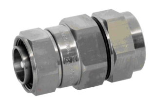
716M-LCF78-D01
7-16 DIN Male Connector for 7/8" Coaxial Cable, OMNI FIT™ Premium,
Straight, O-Ring and compression sealing
- Connector Type : OMNI FIT™ PREMIUM Straight
- Gender : Male
Grounding Kit
Connector grounding kit
High speed grounding kit for CELLFLEX® LCF 78
Grounding Kit, Pre-formed Copper Strap, 1.5m (60") for CELLFLEX® 7/8" Cable
Wall Feedthrough Sealing
Feed through assemblies for 7/8" coaxial cable, 102mm (4"), 1-entry
Feed through assemblies for 7/8" coaxial cable, 102mm (4"), 2-entries
Feed through assemblies for 7/8" coaxial cable, 102mm (4"), 3-entries
Feed through assemblies for 7/8" coaxial cable, 102mm (4"), 4-entries
Wall feed through (without feed through plate)
Tools
Stripping tool for high speed grounding kit GKSPEED-78 series
Hand tool kit for the installation of connectors and grounding kits on CELLFLEX® Cables
Hoisting Grip for Coaxial Cable and Elliptical Waveguide, Closed Lacing
Hoisting Grip for Coaxial Cable and Elliptical Waveguide, Lace-Up
Automated trimming tool, LCF78, UCF 78, OMNI FIT Premium, Trim Series D01
Flaring Tool LCF 7/8" for Universal Trimming Tools
Clamps
Double Multi-block hanger three layers, with angle member adapter
Double Multi-block hanger one layer, with angle member adapter
Single Multi-block hanger one layer, with angle member adapter
Single Multi-block hanger two layer, with angle member adapter
Single Multi-block hanger three layer, with angle member adapter
Cable hanger, non-insulated, bolt-on, for 7/8" coaxial cable and E100, E105 elliptical waveguide
Snap-In Hangers, 7/8", stainless steel (kit of 10)
Stackable Snap-In Hangers, 7/8", stainless steel (kit of 10)
Connectors
4.3-10 Female Connector for 1/2" Coaxial Cable, OMNI FIT™ standard, O-ring sealing
N Male Connector for 7/8" Coaxial Cable, OMNI FIT™ Premium,
Straight, O-Ring and compression sealing
N Female Connector for 7/8" Coaxial Cable, OMNI FIT™ Premium,
Straight, O-Ring and compression sealing
7-16 DIN Male Connector for 7/8" Coaxial Cable, OMNI FIT™ Premium,
Right Angle, O-Ring and compression sealing
7-16 DIN Female Connector for 7/8" Coaxial Cable, OMNI FIT™ Premium, Straight, O-Ring and compression sealing
4.3-10 Male Straight Connector for 7/8" Coaxial Cable, OMNI FIT™ Premium, Polymer claw and compression sealing
4.3-10 Female Straight Connector for 7/8" Coaxial Cable, OMNI FIT™ Premium, Polymer claw and compression sealing
N Male Connector for 7/8" Coaxial Cable, OMNI FIT™ standard, O-ring sealing
7-16 DIN Female Connector for 7/8" Coaxial Cable, OMNI FIT™ standard, O-ring sealing
N Male Connector for 7/8" Coaxial Cable, OMNI FIT™ standard, O-ring sealing
N Female Connector for 7/8" Coaxial Cable, OMNI FIT™ standard, O-ring sealing
7-16 Male Connector for 7/8" Coaxial Cable, OMNI FIT™ standard, O-ring sealing
7-16 DIN Female Connector for 7/8" Coaxial Cable, OMNI FIT™ standard, O-ring sealing
4.3-10 Male Push-Pull Connector for 7/8" Coaxial Cable, OMNI FIT™ standard, O-ring sealing
4.3-10 Male Connector for 7/8" Coaxial Cable, OMNI FIT™ standard, O-ring sealing
4.3-10 Male Hand-Screw Connector for 7/8" Coaxial Cable, OMNI FIT™ standard, O-ring sealing
4.3-10 Female Connector for 7/8" Coaxial Cable, OMNI FIT™ standard, O-ring sealing
7-16 DIN Male Connector for 7/8" Coaxial Cable, OMNI FIT™ Premium,
Straight, O-Ring and compression sealing
7-16 DIN Female Connector for 7/8" Coaxial Cable, OMNI FIT™ Premium, Straight, O-Ring and compression sealing
4.3-10 Female Straight Connector for 7/8" Coaxial Cable, OMNI FIT™ Premium, O-Ring and compression sealing
4.3-10 Male Straight Connector for 7/8" Coaxial Cable, OMNI FIT™ Premium, O-Ring and compression sealing
N Male Connector for 7/8" Coaxial Cable, OMNI FIT™ Premium,
Straight, O-Ring and 360° compression sealing
N Female Connector for 7/8" Coaxial Cable, OMNI FIT™ Premium,
Straight, O-Ring and 360° compression sealing
Coaxial Transmission Line
7/8" CELLFLEX® Lite Low-Loss Foam-Dielectric Coaxial Cable
7/8" CELLFLEX® Premium Attenuation Low-Loss Foam-Dielectric Coaxial Cable
7/8" CELLFLEX® Lite Low-Loss Foam-Dielectric Coaxial Cable
7/8" CELLFLEX® Premium Attenuation Low-Loss Foam-Dielectric Coaxial Cable
7/8" CELLFLEX® Premium Attenuation Low-Loss Foam-Dielectric Coaxial Cable

716F-LCF78-D01
7-16 DIN Female Connector for 7/8" Coaxial Cable, OMNI FIT™ Premium, Straight, O-Ring and compression sealing
- Connector Type : OMNI FIT™ PREMIUM Straight
- Gender : Female
Grounding Kit
Connector grounding kit
High speed grounding kit for CELLFLEX® LCF 78
Grounding Kit, Pre-formed Copper Strap, 1.5m (60") for CELLFLEX® 7/8" Cable
Wall Feedthrough Sealing
Feed through assemblies for 7/8" coaxial cable, 102mm (4"), 1-entry
Feed through assemblies for 7/8" coaxial cable, 102mm (4"), 2-entries
Feed through assemblies for 7/8" coaxial cable, 102mm (4"), 3-entries
Feed through assemblies for 7/8" coaxial cable, 102mm (4"), 4-entries
Wall feed through (without feed through plate)
Tools
Stripping tool for high speed grounding kit GKSPEED-78 series
Hand tool kit for the installation of connectors and grounding kits on CELLFLEX® Cables
Hoisting Grip for Coaxial Cable and Elliptical Waveguide, Closed Lacing
Hoisting Grip for Coaxial Cable and Elliptical Waveguide, Lace-Up
Automated trimming tool, LCF78, UCF 78, OMNI FIT Premium, Trim Series D01
Flaring Tool LCF 7/8" for Universal Trimming Tools
Clamps
Double Multi-block hanger three layers, with angle member adapter
Double Multi-block hanger one layer, with angle member adapter
Single Multi-block hanger one layer, with angle member adapter
Single Multi-block hanger two layer, with angle member adapter
Single Multi-block hanger three layer, with angle member adapter
Cable hanger, non-insulated, bolt-on, for 7/8" coaxial cable and E100, E105 elliptical waveguide
Snap-In Hangers, 7/8", stainless steel (kit of 10)
Stackable Snap-In Hangers, 7/8", stainless steel (kit of 10)
Connectors
4.3-10 Female Connector for 1/2" Coaxial Cable, OMNI FIT™ standard, O-ring sealing
N Male Connector for 7/8" Coaxial Cable, OMNI FIT™ Premium,
Straight, O-Ring and compression sealing
N Female Connector for 7/8" Coaxial Cable, OMNI FIT™ Premium,
Straight, O-Ring and compression sealing
7-16 DIN Male Connector for 7/8" Coaxial Cable, OMNI FIT™ Premium,
Right Angle, O-Ring and compression sealing
7-16 DIN Male Connector for 7/8" Coaxial Cable, OMNI FIT™ Premium,
Straight, O-Ring and compression sealing
4.3-10 Male Straight Connector for 7/8" Coaxial Cable, OMNI FIT™ Premium, Polymer claw and compression sealing
4.3-10 Female Straight Connector for 7/8" Coaxial Cable, OMNI FIT™ Premium, Polymer claw and compression sealing
N Male Connector for 7/8" Coaxial Cable, OMNI FIT™ standard, O-ring sealing
7-16 DIN Female Connector for 7/8" Coaxial Cable, OMNI FIT™ standard, O-ring sealing
N Male Connector for 7/8" Coaxial Cable, OMNI FIT™ standard, O-ring sealing
N Female Connector for 7/8" Coaxial Cable, OMNI FIT™ standard, O-ring sealing
7-16 Male Connector for 7/8" Coaxial Cable, OMNI FIT™ standard, O-ring sealing
7-16 DIN Female Connector for 7/8" Coaxial Cable, OMNI FIT™ standard, O-ring sealing
4.3-10 Male Push-Pull Connector for 7/8" Coaxial Cable, OMNI FIT™ standard, O-ring sealing
4.3-10 Male Connector for 7/8" Coaxial Cable, OMNI FIT™ standard, O-ring sealing
4.3-10 Male Hand-Screw Connector for 7/8" Coaxial Cable, OMNI FIT™ standard, O-ring sealing
4.3-10 Female Connector for 7/8" Coaxial Cable, OMNI FIT™ standard, O-ring sealing
7-16 DIN Male Connector for 7/8" Coaxial Cable, OMNI FIT™ Premium,
Straight, O-Ring and compression sealing
7-16 DIN Female Connector for 7/8" Coaxial Cable, OMNI FIT™ Premium, Straight, O-Ring and compression sealing
4.3-10 Female Straight Connector for 7/8" Coaxial Cable, OMNI FIT™ Premium, O-Ring and compression sealing
4.3-10 Male Straight Connector for 7/8" Coaxial Cable, OMNI FIT™ Premium, O-Ring and compression sealing
N Male Connector for 7/8" Coaxial Cable, OMNI FIT™ Premium,
Straight, O-Ring and 360° compression sealing
N Female Connector for 7/8" Coaxial Cable, OMNI FIT™ Premium,
Straight, O-Ring and 360° compression sealing
Coaxial Transmission Line
7/8" CELLFLEX® Lite Low-Loss Foam-Dielectric Coaxial Cable
7/8" CELLFLEX® Premium Attenuation Low-Loss Foam-Dielectric Coaxial Cable
7/8" CELLFLEX® Lite Low-Loss Foam-Dielectric Coaxial Cable
7/8" CELLFLEX® Premium Attenuation Low-Loss Foam-Dielectric Coaxial Cable
7/8" CELLFLEX® Premium Attenuation Low-Loss Foam-Dielectric Coaxial Cable

43M-LCF78-D01
4.3-10 Male Straight Connector for 7/8" Coaxial Cable, OMNI FIT™ Premium, Polymer claw and compression sealing
- Connector Type : OMNI FIT™ PREMIUM Straight
- Gender : Male
Grounding Kit
Connector grounding kit
High speed grounding kit for CELLFLEX® LCF 78
Grounding Kit, Pre-formed Copper Strap, 1.5m (60") for CELLFLEX® 7/8" Cable
Wall Feedthrough Sealing
Feed through assemblies for 7/8" coaxial cable, 102mm (4"), 1-entry
Feed through assemblies for 7/8" coaxial cable, 102mm (4"), 2-entries
Feed through assemblies for 7/8" coaxial cable, 102mm (4"), 3-entries
Feed through assemblies for 7/8" coaxial cable, 102mm (4"), 4-entries
Wall feed through (without feed through plate)
Tools
Stripping tool for high speed grounding kit GKSPEED-78 series
Hand tool kit for the installation of connectors and grounding kits on CELLFLEX® Cables
Hoisting Grip for Coaxial Cable and Elliptical Waveguide, Closed Lacing
Hoisting Grip for Coaxial Cable and Elliptical Waveguide, Lace-Up
Automated trimming tool, LCF78, UCF 78, OMNI FIT Premium, Trim Series D01
Flaring Tool LCF 7/8" for Universal Trimming Tools
Clamps
Double Multi-block hanger three layers, with angle member adapter
Double Multi-block hanger one layer, with angle member adapter
Single Multi-block hanger one layer, with angle member adapter
Single Multi-block hanger two layer, with angle member adapter
Single Multi-block hanger three layer, with angle member adapter
Cable hanger, non-insulated, bolt-on, for 7/8" coaxial cable and E100, E105 elliptical waveguide
Snap-In Hangers, 7/8", stainless steel (kit of 10)
Stackable Snap-In Hangers, 7/8", stainless steel (kit of 10)
Connectors
4.3-10 Female Connector for 1/2" Coaxial Cable, OMNI FIT™ standard, O-ring sealing
N Male Connector for 7/8" Coaxial Cable, OMNI FIT™ Premium,
Straight, O-Ring and compression sealing
N Female Connector for 7/8" Coaxial Cable, OMNI FIT™ Premium,
Straight, O-Ring and compression sealing
7-16 DIN Male Connector for 7/8" Coaxial Cable, OMNI FIT™ Premium,
Right Angle, O-Ring and compression sealing
7-16 DIN Male Connector for 7/8" Coaxial Cable, OMNI FIT™ Premium,
Straight, O-Ring and compression sealing
7-16 DIN Female Connector for 7/8" Coaxial Cable, OMNI FIT™ Premium, Straight, O-Ring and compression sealing
4.3-10 Female Straight Connector for 7/8" Coaxial Cable, OMNI FIT™ Premium, Polymer claw and compression sealing
N Male Connector for 7/8" Coaxial Cable, OMNI FIT™ standard, O-ring sealing
7-16 DIN Female Connector for 7/8" Coaxial Cable, OMNI FIT™ standard, O-ring sealing
N Male Connector for 7/8" Coaxial Cable, OMNI FIT™ standard, O-ring sealing
N Female Connector for 7/8" Coaxial Cable, OMNI FIT™ standard, O-ring sealing
7-16 Male Connector for 7/8" Coaxial Cable, OMNI FIT™ standard, O-ring sealing
7-16 DIN Female Connector for 7/8" Coaxial Cable, OMNI FIT™ standard, O-ring sealing
4.3-10 Male Push-Pull Connector for 7/8" Coaxial Cable, OMNI FIT™ standard, O-ring sealing
4.3-10 Male Connector for 7/8" Coaxial Cable, OMNI FIT™ standard, O-ring sealing
4.3-10 Male Hand-Screw Connector for 7/8" Coaxial Cable, OMNI FIT™ standard, O-ring sealing
4.3-10 Female Connector for 7/8" Coaxial Cable, OMNI FIT™ standard, O-ring sealing
7-16 DIN Male Connector for 7/8" Coaxial Cable, OMNI FIT™ Premium,
Straight, O-Ring and compression sealing
7-16 DIN Female Connector for 7/8" Coaxial Cable, OMNI FIT™ Premium, Straight, O-Ring and compression sealing
4.3-10 Female Straight Connector for 7/8" Coaxial Cable, OMNI FIT™ Premium, O-Ring and compression sealing
4.3-10 Male Straight Connector for 7/8" Coaxial Cable, OMNI FIT™ Premium, O-Ring and compression sealing
N Male Connector for 7/8" Coaxial Cable, OMNI FIT™ Premium,
Straight, O-Ring and 360° compression sealing
N Female Connector for 7/8" Coaxial Cable, OMNI FIT™ Premium,
Straight, O-Ring and 360° compression sealing
Coaxial Transmission Line
7/8" CELLFLEX® Premium Attenuation Low-Loss Foam-Dielectric Coaxial Cable
7/8" CELLFLEX® Premium Attenuation Low-Loss Foam-Dielectric Coaxial Cable
7/8" CELLFLEX® Premium Attenuation Low-Loss Foam-Dielectric Coaxial Cable

43F-LCF78-D01
4.3-10 Female Straight Connector for 7/8" Coaxial Cable, OMNI FIT™ Premium, Polymer claw and compression sealing
- Connector Type : OMNI FIT™ PREMIUM Straight
- Gender : Female
Grounding Kit
Connector grounding kit
High speed grounding kit for CELLFLEX® LCF 78
Grounding Kit, Pre-formed Copper Strap, 1.5m (60") for CELLFLEX® 7/8" Cable
Wall Feedthrough Sealing
Feed through assemblies for 7/8" coaxial cable, 102mm (4"), 1-entry
Feed through assemblies for 7/8" coaxial cable, 102mm (4"), 2-entries
Feed through assemblies for 7/8" coaxial cable, 102mm (4"), 3-entries
Feed through assemblies for 7/8" coaxial cable, 102mm (4"), 4-entries
Wall feed through (without feed through plate)
Tools
Stripping tool for high speed grounding kit GKSPEED-78 series
Hand tool kit for the installation of connectors and grounding kits on CELLFLEX® Cables
Hoisting Grip for Coaxial Cable and Elliptical Waveguide, Closed Lacing
Hoisting Grip for Coaxial Cable and Elliptical Waveguide, Lace-Up
Automated trimming tool, LCF78, UCF 78, OMNI FIT Premium, Trim Series D01
Flaring Tool LCF 7/8" for Universal Trimming Tools
Clamps
Double Multi-block hanger three layers, with angle member adapter
Double Multi-block hanger one layer, with angle member adapter
Single Multi-block hanger one layer, with angle member adapter
Single Multi-block hanger two layer, with angle member adapter
Single Multi-block hanger three layer, with angle member adapter
Cable hanger, non-insulated, bolt-on, for 7/8" coaxial cable and E100, E105 elliptical waveguide
Snap-In Hangers, 7/8", stainless steel (kit of 10)
Stackable Snap-In Hangers, 7/8", stainless steel (kit of 10)
Connectors
4.3-10 Female Connector for 1/2" Coaxial Cable, OMNI FIT™ standard, O-ring sealing
N Male Connector for 7/8" Coaxial Cable, OMNI FIT™ Premium,
Straight, O-Ring and compression sealing
N Female Connector for 7/8" Coaxial Cable, OMNI FIT™ Premium,
Straight, O-Ring and compression sealing
7-16 DIN Male Connector for 7/8" Coaxial Cable, OMNI FIT™ Premium,
Right Angle, O-Ring and compression sealing
7-16 DIN Male Connector for 7/8" Coaxial Cable, OMNI FIT™ Premium,
Straight, O-Ring and compression sealing
7-16 DIN Female Connector for 7/8" Coaxial Cable, OMNI FIT™ Premium, Straight, O-Ring and compression sealing
4.3-10 Male Straight Connector for 7/8" Coaxial Cable, OMNI FIT™ Premium, Polymer claw and compression sealing
N Male Connector for 7/8" Coaxial Cable, OMNI FIT™ standard, O-ring sealing
7-16 DIN Female Connector for 7/8" Coaxial Cable, OMNI FIT™ standard, O-ring sealing
N Male Connector for 7/8" Coaxial Cable, OMNI FIT™ standard, O-ring sealing
N Female Connector for 7/8" Coaxial Cable, OMNI FIT™ standard, O-ring sealing
7-16 Male Connector for 7/8" Coaxial Cable, OMNI FIT™ standard, O-ring sealing
7-16 DIN Female Connector for 7/8" Coaxial Cable, OMNI FIT™ standard, O-ring sealing
4.3-10 Male Push-Pull Connector for 7/8" Coaxial Cable, OMNI FIT™ standard, O-ring sealing
4.3-10 Male Connector for 7/8" Coaxial Cable, OMNI FIT™ standard, O-ring sealing
4.3-10 Male Hand-Screw Connector for 7/8" Coaxial Cable, OMNI FIT™ standard, O-ring sealing
4.3-10 Female Connector for 7/8" Coaxial Cable, OMNI FIT™ standard, O-ring sealing
7-16 DIN Male Connector for 7/8" Coaxial Cable, OMNI FIT™ Premium,
Straight, O-Ring and compression sealing
7-16 DIN Female Connector for 7/8" Coaxial Cable, OMNI FIT™ Premium, Straight, O-Ring and compression sealing
4.3-10 Female Straight Connector for 7/8" Coaxial Cable, OMNI FIT™ Premium, O-Ring and compression sealing
4.3-10 Male Straight Connector for 7/8" Coaxial Cable, OMNI FIT™ Premium, O-Ring and compression sealing
N Male Connector for 7/8" Coaxial Cable, OMNI FIT™ Premium,
Straight, O-Ring and 360° compression sealing
N Female Connector for 7/8" Coaxial Cable, OMNI FIT™ Premium,
Straight, O-Ring and 360° compression sealing
Coaxial Transmission Line
7/8" CELLFLEX® Premium Attenuation Low-Loss Foam-Dielectric Coaxial Cable
7/8" CELLFLEX® Premium Attenuation Low-Loss Foam-Dielectric Coaxial Cable
7/8" CELLFLEX® Premium Attenuation Low-Loss Foam-Dielectric Coaxial Cable

NM-LCF78-C02
N Male Connector for 7/8" Coaxial Cable, OMNI FIT™ standard, O-ring sealing
- Connector Type : OMNI FIT™ Standard
- Gender : Male
Grounding Kit
Connector grounding kit
High speed grounding kit for CELLFLEX® LCF 78
Grounding Kit, Pre-formed Copper Strap, 1.5m (60") for CELLFLEX® 7/8" Cable
Wall Feedthrough Sealing
Feed through assemblies for 7/8" coaxial cable, 102mm (4"), 1-entry
Feed through assemblies for 7/8" coaxial cable, 102mm (4"), 2-entries
Feed through assemblies for 7/8" coaxial cable, 102mm (4"), 3-entries
Feed through assemblies for 7/8" coaxial cable, 102mm (4"), 4-entries
Wall feed through (without feed through plate)
Tools
Stripping tool for high speed grounding kit GKSPEED-78 series
Hand tool kit for the installation of connectors and grounding kits on CELLFLEX® Cables
Hoisting Grip for Coaxial Cable and Elliptical Waveguide, Closed Lacing
Hoisting Grip for Coaxial Cable and Elliptical Waveguide, Lace-Up
Automated trimming tool, LCF78, UCF 78, OMNI FIT Premium, Trim Series D01
Flaring Tool LCF 7/8" for Universal Trimming Tools
Clamps
Double Multi-block hanger three layers, with angle member adapter
Double Multi-block hanger one layer, with angle member adapter
Single Multi-block hanger one layer, with angle member adapter
Single Multi-block hanger two layer, with angle member adapter
Single Multi-block hanger three layer, with angle member adapter
Cable hanger, non-insulated, bolt-on, for 7/8" coaxial cable and E100, E105 elliptical waveguide
Snap-In Hangers, 7/8", stainless steel (kit of 10)
Stackable Snap-In Hangers, 7/8", stainless steel (kit of 10)
Connectors
4.3-10 Female Connector for 1/2" Coaxial Cable, OMNI FIT™ standard, O-ring sealing
N Male Connector for 7/8" Coaxial Cable, OMNI FIT™ Premium,
Straight, O-Ring and compression sealing
N Female Connector for 7/8" Coaxial Cable, OMNI FIT™ Premium,
Straight, O-Ring and compression sealing
7-16 DIN Male Connector for 7/8" Coaxial Cable, OMNI FIT™ Premium,
Right Angle, O-Ring and compression sealing
7-16 DIN Male Connector for 7/8" Coaxial Cable, OMNI FIT™ Premium,
Straight, O-Ring and compression sealing
7-16 DIN Female Connector for 7/8" Coaxial Cable, OMNI FIT™ Premium, Straight, O-Ring and compression sealing
4.3-10 Male Straight Connector for 7/8" Coaxial Cable, OMNI FIT™ Premium, Polymer claw and compression sealing
4.3-10 Female Straight Connector for 7/8" Coaxial Cable, OMNI FIT™ Premium, Polymer claw and compression sealing
7-16 DIN Female Connector for 7/8" Coaxial Cable, OMNI FIT™ standard, O-ring sealing
N Male Connector for 7/8" Coaxial Cable, OMNI FIT™ standard, O-ring sealing
N Female Connector for 7/8" Coaxial Cable, OMNI FIT™ standard, O-ring sealing
7-16 Male Connector for 7/8" Coaxial Cable, OMNI FIT™ standard, O-ring sealing
7-16 DIN Female Connector for 7/8" Coaxial Cable, OMNI FIT™ standard, O-ring sealing
4.3-10 Male Push-Pull Connector for 7/8" Coaxial Cable, OMNI FIT™ standard, O-ring sealing
4.3-10 Male Connector for 7/8" Coaxial Cable, OMNI FIT™ standard, O-ring sealing
4.3-10 Male Hand-Screw Connector for 7/8" Coaxial Cable, OMNI FIT™ standard, O-ring sealing
4.3-10 Female Connector for 7/8" Coaxial Cable, OMNI FIT™ standard, O-ring sealing
7-16 DIN Male Connector for 7/8" Coaxial Cable, OMNI FIT™ Premium,
Straight, O-Ring and compression sealing
7-16 DIN Female Connector for 7/8" Coaxial Cable, OMNI FIT™ Premium, Straight, O-Ring and compression sealing
4.3-10 Female Straight Connector for 7/8" Coaxial Cable, OMNI FIT™ Premium, O-Ring and compression sealing
4.3-10 Male Straight Connector for 7/8" Coaxial Cable, OMNI FIT™ Premium, O-Ring and compression sealing
N Male Connector for 7/8" Coaxial Cable, OMNI FIT™ Premium,
Straight, O-Ring and 360° compression sealing
N Female Connector for 7/8" Coaxial Cable, OMNI FIT™ Premium,
Straight, O-Ring and 360° compression sealing
Coaxial Transmission Line
7/8" CELLFLEX® Lite Low-Loss Foam-Dielectric Coaxial Cable
7/8" CELLFLEX® Premium Attenuation Low-Loss Foam-Dielectric Coaxial Cable
7/8" CELLFLEX® Lite Low-Loss Foam-Dielectric Coaxial Cable
7/8" CELLFLEX® Premium Attenuation Low-Loss Foam-Dielectric Coaxial Cable
7/8" CELLFLEX® Premium Attenuation Low-Loss Foam-Dielectric Coaxial Cable

716F-LCF78-C02
7-16 DIN Female Connector for 7/8" Coaxial Cable, OMNI FIT™ standard, O-ring sealing
- Connector Type : OMNI FIT™ Standard
- Gender : Female
Grounding Kit
Connector grounding kit
High speed grounding kit for CELLFLEX® LCF 78
Grounding Kit, Pre-formed Copper Strap, 1.5m (60") for CELLFLEX® 7/8" Cable
Wall Feedthrough Sealing
Feed through assemblies for 7/8" coaxial cable, 102mm (4"), 1-entry
Feed through assemblies for 7/8" coaxial cable, 102mm (4"), 2-entries
Feed through assemblies for 7/8" coaxial cable, 102mm (4"), 3-entries
Feed through assemblies for 7/8" coaxial cable, 102mm (4"), 4-entries
Wall feed through (without feed through plate)
Tools
Stripping tool for high speed grounding kit GKSPEED-78 series
Hand tool kit for the installation of connectors and grounding kits on CELLFLEX® Cables
Hoisting Grip for Coaxial Cable and Elliptical Waveguide, Closed Lacing
Hoisting Grip for Coaxial Cable and Elliptical Waveguide, Lace-Up
Automated trimming tool, LCF78, UCF 78, OMNI FIT Premium, Trim Series D01
Flaring Tool LCF 7/8" for Universal Trimming Tools
Clamps
Double Multi-block hanger three layers, with angle member adapter
Double Multi-block hanger one layer, with angle member adapter
Single Multi-block hanger one layer, with angle member adapter
Single Multi-block hanger two layer, with angle member adapter
Single Multi-block hanger three layer, with angle member adapter
Cable hanger, non-insulated, bolt-on, for 7/8" coaxial cable and E100, E105 elliptical waveguide
Snap-In Hangers, 7/8", stainless steel (kit of 10)
Stackable Snap-In Hangers, 7/8", stainless steel (kit of 10)
Connectors
4.3-10 Female Connector for 1/2" Coaxial Cable, OMNI FIT™ standard, O-ring sealing
N Male Connector for 7/8" Coaxial Cable, OMNI FIT™ Premium,
Straight, O-Ring and compression sealing
N Female Connector for 7/8" Coaxial Cable, OMNI FIT™ Premium,
Straight, O-Ring and compression sealing
7-16 DIN Male Connector for 7/8" Coaxial Cable, OMNI FIT™ Premium,
Right Angle, O-Ring and compression sealing
7-16 DIN Male Connector for 7/8" Coaxial Cable, OMNI FIT™ Premium,
Straight, O-Ring and compression sealing
7-16 DIN Female Connector for 7/8" Coaxial Cable, OMNI FIT™ Premium, Straight, O-Ring and compression sealing
4.3-10 Male Straight Connector for 7/8" Coaxial Cable, OMNI FIT™ Premium, Polymer claw and compression sealing
4.3-10 Female Straight Connector for 7/8" Coaxial Cable, OMNI FIT™ Premium, Polymer claw and compression sealing
N Male Connector for 7/8" Coaxial Cable, OMNI FIT™ standard, O-ring sealing
N Male Connector for 7/8" Coaxial Cable, OMNI FIT™ standard, O-ring sealing
N Female Connector for 7/8" Coaxial Cable, OMNI FIT™ standard, O-ring sealing
7-16 Male Connector for 7/8" Coaxial Cable, OMNI FIT™ standard, O-ring sealing
7-16 DIN Female Connector for 7/8" Coaxial Cable, OMNI FIT™ standard, O-ring sealing
4.3-10 Male Push-Pull Connector for 7/8" Coaxial Cable, OMNI FIT™ standard, O-ring sealing
4.3-10 Male Connector for 7/8" Coaxial Cable, OMNI FIT™ standard, O-ring sealing
4.3-10 Male Hand-Screw Connector for 7/8" Coaxial Cable, OMNI FIT™ standard, O-ring sealing
4.3-10 Female Connector for 7/8" Coaxial Cable, OMNI FIT™ standard, O-ring sealing
7-16 DIN Male Connector for 7/8" Coaxial Cable, OMNI FIT™ Premium,
Straight, O-Ring and compression sealing
7-16 DIN Female Connector for 7/8" Coaxial Cable, OMNI FIT™ Premium, Straight, O-Ring and compression sealing
4.3-10 Female Straight Connector for 7/8" Coaxial Cable, OMNI FIT™ Premium, O-Ring and compression sealing
4.3-10 Male Straight Connector for 7/8" Coaxial Cable, OMNI FIT™ Premium, O-Ring and compression sealing
N Male Connector for 7/8" Coaxial Cable, OMNI FIT™ Premium,
Straight, O-Ring and 360° compression sealing
N Female Connector for 7/8" Coaxial Cable, OMNI FIT™ Premium,
Straight, O-Ring and 360° compression sealing
Coaxial Transmission Line
7/8" CELLFLEX® Lite Low-Loss Foam-Dielectric Coaxial Cable
7/8" CELLFLEX® Premium Attenuation Low-Loss Foam-Dielectric Coaxial Cable
7/8" CELLFLEX® Lite Low-Loss Foam-Dielectric Coaxial Cable
7/8" CELLFLEX® Premium Attenuation Low-Loss Foam-Dielectric Coaxial Cable
7/8" CELLFLEX® Premium Attenuation Low-Loss Foam-Dielectric Coaxial Cable

NM-LCF78-C03
N Male Connector for 7/8" Coaxial Cable, OMNI FIT™ standard, O-ring sealing
- Connector Type : OMNI FIT™ Standard
- Gender : Male
Grounding Kit
Connector grounding kit
High speed grounding kit for CELLFLEX® LCF 78
Grounding Kit, Pre-formed Copper Strap, 1.5m (60") for CELLFLEX® 7/8" Cable
Wall Feedthrough Sealing
Feed through assemblies for 7/8" coaxial cable, 102mm (4"), 1-entry
Feed through assemblies for 7/8" coaxial cable, 102mm (4"), 2-entries
Feed through assemblies for 7/8" coaxial cable, 102mm (4"), 3-entries
Feed through assemblies for 7/8" coaxial cable, 102mm (4"), 4-entries
Wall feed through (without feed through plate)
Tools
Stripping tool for high speed grounding kit GKSPEED-78 series
Hand tool kit for the installation of connectors and grounding kits on CELLFLEX® Cables
Hoisting Grip for Coaxial Cable and Elliptical Waveguide, Closed Lacing
Hoisting Grip for Coaxial Cable and Elliptical Waveguide, Lace-Up
Automated trimming tool, LCF78, UCF 78, OMNI FIT Premium, Trim Series D01
Flaring Tool LCF 7/8" for Universal Trimming Tools
Clamps
Double Multi-block hanger three layers, with angle member adapter
Double Multi-block hanger one layer, with angle member adapter
Single Multi-block hanger one layer, with angle member adapter
Single Multi-block hanger two layer, with angle member adapter
Single Multi-block hanger three layer, with angle member adapter
Cable hanger, non-insulated, bolt-on, for 7/8" coaxial cable and E100, E105 elliptical waveguide
Snap-In Hangers, 7/8", stainless steel (kit of 10)
Stackable Snap-In Hangers, 7/8", stainless steel (kit of 10)
Connectors
4.3-10 Female Connector for 1/2" Coaxial Cable, OMNI FIT™ standard, O-ring sealing
N Male Connector for 7/8" Coaxial Cable, OMNI FIT™ Premium,
Straight, O-Ring and compression sealing
N Female Connector for 7/8" Coaxial Cable, OMNI FIT™ Premium,
Straight, O-Ring and compression sealing
7-16 DIN Male Connector for 7/8" Coaxial Cable, OMNI FIT™ Premium,
Right Angle, O-Ring and compression sealing
7-16 DIN Male Connector for 7/8" Coaxial Cable, OMNI FIT™ Premium,
Straight, O-Ring and compression sealing
7-16 DIN Female Connector for 7/8" Coaxial Cable, OMNI FIT™ Premium, Straight, O-Ring and compression sealing
4.3-10 Male Straight Connector for 7/8" Coaxial Cable, OMNI FIT™ Premium, Polymer claw and compression sealing
4.3-10 Female Straight Connector for 7/8" Coaxial Cable, OMNI FIT™ Premium, Polymer claw and compression sealing
N Male Connector for 7/8" Coaxial Cable, OMNI FIT™ standard, O-ring sealing
7-16 DIN Female Connector for 7/8" Coaxial Cable, OMNI FIT™ standard, O-ring sealing
N Female Connector for 7/8" Coaxial Cable, OMNI FIT™ standard, O-ring sealing
7-16 Male Connector for 7/8" Coaxial Cable, OMNI FIT™ standard, O-ring sealing
7-16 DIN Female Connector for 7/8" Coaxial Cable, OMNI FIT™ standard, O-ring sealing
4.3-10 Male Push-Pull Connector for 7/8" Coaxial Cable, OMNI FIT™ standard, O-ring sealing
4.3-10 Male Connector for 7/8" Coaxial Cable, OMNI FIT™ standard, O-ring sealing
4.3-10 Male Hand-Screw Connector for 7/8" Coaxial Cable, OMNI FIT™ standard, O-ring sealing
4.3-10 Female Connector for 7/8" Coaxial Cable, OMNI FIT™ standard, O-ring sealing
7-16 DIN Male Connector for 7/8" Coaxial Cable, OMNI FIT™ Premium,
Straight, O-Ring and compression sealing
7-16 DIN Female Connector for 7/8" Coaxial Cable, OMNI FIT™ Premium, Straight, O-Ring and compression sealing
4.3-10 Female Straight Connector for 7/8" Coaxial Cable, OMNI FIT™ Premium, O-Ring and compression sealing
4.3-10 Male Straight Connector for 7/8" Coaxial Cable, OMNI FIT™ Premium, O-Ring and compression sealing
N Male Connector for 7/8" Coaxial Cable, OMNI FIT™ Premium,
Straight, O-Ring and 360° compression sealing
N Female Connector for 7/8" Coaxial Cable, OMNI FIT™ Premium,
Straight, O-Ring and 360° compression sealing
Coaxial Transmission Line
7/8" CELLFLEX® Premium Attenuation Low-Loss Foam-Dielectric Coaxial Cable
7/8" CELLFLEX® Premium Attenuation Low-Loss Foam-Dielectric Coaxial Cable
7/8" CELLFLEX® Premium Attenuation Low-Loss Foam-Dielectric Coaxial Cable

NF-LCF78-C03
N Female Connector for 7/8" Coaxial Cable, OMNI FIT™ standard, O-ring sealing
- Connector Type : OMNI FIT™ Standard
- Gender : Female
Grounding Kit
Connector grounding kit
High speed grounding kit for CELLFLEX® LCF 78
Grounding Kit, Pre-formed Copper Strap, 1.5m (60") for CELLFLEX® 7/8" Cable
Wall Feedthrough Sealing
Feed through assemblies for 7/8" coaxial cable, 102mm (4"), 1-entry
Feed through assemblies for 7/8" coaxial cable, 102mm (4"), 2-entries
Feed through assemblies for 7/8" coaxial cable, 102mm (4"), 3-entries
Feed through assemblies for 7/8" coaxial cable, 102mm (4"), 4-entries
Wall feed through (without feed through plate)
Tools
Stripping tool for high speed grounding kit GKSPEED-78 series
Hand tool kit for the installation of connectors and grounding kits on CELLFLEX® Cables
Hoisting Grip for Coaxial Cable and Elliptical Waveguide, Closed Lacing
Hoisting Grip for Coaxial Cable and Elliptical Waveguide, Lace-Up
Automated trimming tool, LCF78, UCF 78, OMNI FIT Premium, Trim Series D01
Flaring Tool LCF 7/8" for Universal Trimming Tools
Clamps
Double Multi-block hanger three layers, with angle member adapter
Double Multi-block hanger one layer, with angle member adapter
Single Multi-block hanger one layer, with angle member adapter
Single Multi-block hanger two layer, with angle member adapter
Single Multi-block hanger three layer, with angle member adapter
Cable hanger, non-insulated, bolt-on, for 7/8" coaxial cable and E100, E105 elliptical waveguide
Snap-In Hangers, 7/8", stainless steel (kit of 10)
Stackable Snap-In Hangers, 7/8", stainless steel (kit of 10)
Connectors
4.3-10 Female Connector for 1/2" Coaxial Cable, OMNI FIT™ standard, O-ring sealing
N Male Connector for 7/8" Coaxial Cable, OMNI FIT™ Premium,
Straight, O-Ring and compression sealing
N Female Connector for 7/8" Coaxial Cable, OMNI FIT™ Premium,
Straight, O-Ring and compression sealing
7-16 DIN Male Connector for 7/8" Coaxial Cable, OMNI FIT™ Premium,
Right Angle, O-Ring and compression sealing
7-16 DIN Male Connector for 7/8" Coaxial Cable, OMNI FIT™ Premium,
Straight, O-Ring and compression sealing
7-16 DIN Female Connector for 7/8" Coaxial Cable, OMNI FIT™ Premium, Straight, O-Ring and compression sealing
4.3-10 Male Straight Connector for 7/8" Coaxial Cable, OMNI FIT™ Premium, Polymer claw and compression sealing
4.3-10 Female Straight Connector for 7/8" Coaxial Cable, OMNI FIT™ Premium, Polymer claw and compression sealing
N Male Connector for 7/8" Coaxial Cable, OMNI FIT™ standard, O-ring sealing
7-16 DIN Female Connector for 7/8" Coaxial Cable, OMNI FIT™ standard, O-ring sealing
N Male Connector for 7/8" Coaxial Cable, OMNI FIT™ standard, O-ring sealing
7-16 Male Connector for 7/8" Coaxial Cable, OMNI FIT™ standard, O-ring sealing
7-16 DIN Female Connector for 7/8" Coaxial Cable, OMNI FIT™ standard, O-ring sealing
4.3-10 Male Push-Pull Connector for 7/8" Coaxial Cable, OMNI FIT™ standard, O-ring sealing
4.3-10 Male Connector for 7/8" Coaxial Cable, OMNI FIT™ standard, O-ring sealing
4.3-10 Male Hand-Screw Connector for 7/8" Coaxial Cable, OMNI FIT™ standard, O-ring sealing
4.3-10 Female Connector for 7/8" Coaxial Cable, OMNI FIT™ standard, O-ring sealing
7-16 DIN Male Connector for 7/8" Coaxial Cable, OMNI FIT™ Premium,
Straight, O-Ring and compression sealing
7-16 DIN Female Connector for 7/8" Coaxial Cable, OMNI FIT™ Premium, Straight, O-Ring and compression sealing
4.3-10 Female Straight Connector for 7/8" Coaxial Cable, OMNI FIT™ Premium, O-Ring and compression sealing
4.3-10 Male Straight Connector for 7/8" Coaxial Cable, OMNI FIT™ Premium, O-Ring and compression sealing
N Male Connector for 7/8" Coaxial Cable, OMNI FIT™ Premium,
Straight, O-Ring and 360° compression sealing
N Female Connector for 7/8" Coaxial Cable, OMNI FIT™ Premium,
Straight, O-Ring and 360° compression sealing
Coaxial Transmission Line
7/8" CELLFLEX® Premium Attenuation Low-Loss Foam-Dielectric Coaxial Cable
7/8" CELLFLEX® Premium Attenuation Low-Loss Foam-Dielectric Coaxial Cable
7/8" CELLFLEX® Premium Attenuation Low-Loss Foam-Dielectric Coaxial Cable

716M-LCF78-C03
7-16 Male Connector for 7/8" Coaxial Cable, OMNI FIT™ standard, O-ring sealing
- Connector Type : OMNI FIT™ Standard
- Gender : Male
Grounding Kit
Connector grounding kit
High speed grounding kit for CELLFLEX® LCF 78
Grounding Kit, Pre-formed Copper Strap, 1.5m (60") for CELLFLEX® 7/8" Cable
Wall Feedthrough Sealing
Feed through assemblies for 7/8" coaxial cable, 102mm (4"), 1-entry
Feed through assemblies for 7/8" coaxial cable, 102mm (4"), 2-entries
Feed through assemblies for 7/8" coaxial cable, 102mm (4"), 3-entries
Feed through assemblies for 7/8" coaxial cable, 102mm (4"), 4-entries
Wall feed through (without feed through plate)
Tools
Stripping tool for high speed grounding kit GKSPEED-78 series
Hand tool kit for the installation of connectors and grounding kits on CELLFLEX® Cables
Hoisting Grip for Coaxial Cable and Elliptical Waveguide, Closed Lacing
Hoisting Grip for Coaxial Cable and Elliptical Waveguide, Lace-Up
Automated trimming tool, LCF78, UCF 78, OMNI FIT Premium, Trim Series D01
Flaring Tool LCF 7/8" for Universal Trimming Tools
Clamps
Double Multi-block hanger three layers, with angle member adapter
Double Multi-block hanger one layer, with angle member adapter
Single Multi-block hanger one layer, with angle member adapter
Single Multi-block hanger two layer, with angle member adapter
Single Multi-block hanger three layer, with angle member adapter
Cable hanger, non-insulated, bolt-on, for 7/8" coaxial cable and E100, E105 elliptical waveguide
Snap-In Hangers, 7/8", stainless steel (kit of 10)
Stackable Snap-In Hangers, 7/8", stainless steel (kit of 10)
Connectors
4.3-10 Female Connector for 1/2" Coaxial Cable, OMNI FIT™ standard, O-ring sealing
N Male Connector for 7/8" Coaxial Cable, OMNI FIT™ Premium,
Straight, O-Ring and compression sealing
N Female Connector for 7/8" Coaxial Cable, OMNI FIT™ Premium,
Straight, O-Ring and compression sealing
7-16 DIN Male Connector for 7/8" Coaxial Cable, OMNI FIT™ Premium,
Right Angle, O-Ring and compression sealing
7-16 DIN Male Connector for 7/8" Coaxial Cable, OMNI FIT™ Premium,
Straight, O-Ring and compression sealing
7-16 DIN Female Connector for 7/8" Coaxial Cable, OMNI FIT™ Premium, Straight, O-Ring and compression sealing
4.3-10 Male Straight Connector for 7/8" Coaxial Cable, OMNI FIT™ Premium, Polymer claw and compression sealing
4.3-10 Female Straight Connector for 7/8" Coaxial Cable, OMNI FIT™ Premium, Polymer claw and compression sealing
N Male Connector for 7/8" Coaxial Cable, OMNI FIT™ standard, O-ring sealing
7-16 DIN Female Connector for 7/8" Coaxial Cable, OMNI FIT™ standard, O-ring sealing
N Male Connector for 7/8" Coaxial Cable, OMNI FIT™ standard, O-ring sealing
N Female Connector for 7/8" Coaxial Cable, OMNI FIT™ standard, O-ring sealing
7-16 DIN Female Connector for 7/8" Coaxial Cable, OMNI FIT™ standard, O-ring sealing
4.3-10 Male Push-Pull Connector for 7/8" Coaxial Cable, OMNI FIT™ standard, O-ring sealing
4.3-10 Male Connector for 7/8" Coaxial Cable, OMNI FIT™ standard, O-ring sealing
4.3-10 Male Hand-Screw Connector for 7/8" Coaxial Cable, OMNI FIT™ standard, O-ring sealing
4.3-10 Female Connector for 7/8" Coaxial Cable, OMNI FIT™ standard, O-ring sealing
7-16 DIN Male Connector for 7/8" Coaxial Cable, OMNI FIT™ Premium,
Straight, O-Ring and compression sealing
7-16 DIN Female Connector for 7/8" Coaxial Cable, OMNI FIT™ Premium, Straight, O-Ring and compression sealing
4.3-10 Female Straight Connector for 7/8" Coaxial Cable, OMNI FIT™ Premium, O-Ring and compression sealing
4.3-10 Male Straight Connector for 7/8" Coaxial Cable, OMNI FIT™ Premium, O-Ring and compression sealing
N Male Connector for 7/8" Coaxial Cable, OMNI FIT™ Premium,
Straight, O-Ring and 360° compression sealing
N Female Connector for 7/8" Coaxial Cable, OMNI FIT™ Premium,
Straight, O-Ring and 360° compression sealing
Coaxial Transmission Line
7/8" CELLFLEX® Premium Attenuation Low-Loss Foam-Dielectric Coaxial Cable
7/8" CELLFLEX® Premium Attenuation Low-Loss Foam-Dielectric Coaxial Cable
7/8" CELLFLEX® Premium Attenuation Low-Loss Foam-Dielectric Coaxial Cable

716F-LCF78-C03
7-16 DIN Female Connector for 7/8" Coaxial Cable, OMNI FIT™ standard, O-ring sealing
- Connector Type : OMNI FIT™ Standard
- Gender : Female
Grounding Kit
Connector grounding kit
High speed grounding kit for CELLFLEX® LCF 78
Grounding Kit, Pre-formed Copper Strap, 1.5m (60") for CELLFLEX® 7/8" Cable
Wall Feedthrough Sealing
Feed through assemblies for 7/8" coaxial cable, 102mm (4"), 1-entry
Feed through assemblies for 7/8" coaxial cable, 102mm (4"), 2-entries
Feed through assemblies for 7/8" coaxial cable, 102mm (4"), 3-entries
Feed through assemblies for 7/8" coaxial cable, 102mm (4"), 4-entries
Wall feed through (without feed through plate)
Tools
Stripping tool for high speed grounding kit GKSPEED-78 series
Hand tool kit for the installation of connectors and grounding kits on CELLFLEX® Cables
Hoisting Grip for Coaxial Cable and Elliptical Waveguide, Closed Lacing
Hoisting Grip for Coaxial Cable and Elliptical Waveguide, Lace-Up
Automated trimming tool, LCF78, UCF 78, OMNI FIT Premium, Trim Series D01
Flaring Tool LCF 7/8" for Universal Trimming Tools
Clamps
Double Multi-block hanger three layers, with angle member adapter
Double Multi-block hanger one layer, with angle member adapter
Single Multi-block hanger one layer, with angle member adapter
Single Multi-block hanger two layer, with angle member adapter
Single Multi-block hanger three layer, with angle member adapter
Cable hanger, non-insulated, bolt-on, for 7/8" coaxial cable and E100, E105 elliptical waveguide
Snap-In Hangers, 7/8", stainless steel (kit of 10)
Stackable Snap-In Hangers, 7/8", stainless steel (kit of 10)
Connectors
4.3-10 Female Connector for 1/2" Coaxial Cable, OMNI FIT™ standard, O-ring sealing
N Male Connector for 7/8" Coaxial Cable, OMNI FIT™ Premium,
Straight, O-Ring and compression sealing
N Female Connector for 7/8" Coaxial Cable, OMNI FIT™ Premium,
Straight, O-Ring and compression sealing
7-16 DIN Male Connector for 7/8" Coaxial Cable, OMNI FIT™ Premium,
Right Angle, O-Ring and compression sealing
7-16 DIN Male Connector for 7/8" Coaxial Cable, OMNI FIT™ Premium,
Straight, O-Ring and compression sealing
7-16 DIN Female Connector for 7/8" Coaxial Cable, OMNI FIT™ Premium, Straight, O-Ring and compression sealing
4.3-10 Male Straight Connector for 7/8" Coaxial Cable, OMNI FIT™ Premium, Polymer claw and compression sealing
4.3-10 Female Straight Connector for 7/8" Coaxial Cable, OMNI FIT™ Premium, Polymer claw and compression sealing
N Male Connector for 7/8" Coaxial Cable, OMNI FIT™ standard, O-ring sealing
7-16 DIN Female Connector for 7/8" Coaxial Cable, OMNI FIT™ standard, O-ring sealing
N Male Connector for 7/8" Coaxial Cable, OMNI FIT™ standard, O-ring sealing
N Female Connector for 7/8" Coaxial Cable, OMNI FIT™ standard, O-ring sealing
7-16 Male Connector for 7/8" Coaxial Cable, OMNI FIT™ standard, O-ring sealing
4.3-10 Male Push-Pull Connector for 7/8" Coaxial Cable, OMNI FIT™ standard, O-ring sealing
4.3-10 Male Connector for 7/8" Coaxial Cable, OMNI FIT™ standard, O-ring sealing
4.3-10 Male Hand-Screw Connector for 7/8" Coaxial Cable, OMNI FIT™ standard, O-ring sealing
4.3-10 Female Connector for 7/8" Coaxial Cable, OMNI FIT™ standard, O-ring sealing
7-16 DIN Male Connector for 7/8" Coaxial Cable, OMNI FIT™ Premium,
Straight, O-Ring and compression sealing
7-16 DIN Female Connector for 7/8" Coaxial Cable, OMNI FIT™ Premium, Straight, O-Ring and compression sealing
4.3-10 Female Straight Connector for 7/8" Coaxial Cable, OMNI FIT™ Premium, O-Ring and compression sealing
4.3-10 Male Straight Connector for 7/8" Coaxial Cable, OMNI FIT™ Premium, O-Ring and compression sealing
N Male Connector for 7/8" Coaxial Cable, OMNI FIT™ Premium,
Straight, O-Ring and 360° compression sealing
N Female Connector for 7/8" Coaxial Cable, OMNI FIT™ Premium,
Straight, O-Ring and 360° compression sealing
Coaxial Transmission Line
7/8" CELLFLEX® Lite Low-Loss Foam-Dielectric Coaxial Cable
7/8" CELLFLEX® Premium Attenuation Low-Loss Foam-Dielectric Coaxial Cable
7/8" CELLFLEX® Lite Low-Loss Foam-Dielectric Coaxial Cable
7/8" CELLFLEX® Premium Attenuation Low-Loss Foam-Dielectric Coaxial Cable
7/8" CELLFLEX® Premium Attenuation Low-Loss Foam-Dielectric Coaxial Cable

43MP-LCF78-C03
4.3-10 Male Push-Pull Connector for 7/8" Coaxial Cable, OMNI FIT™ standard, O-ring sealing
- Connector Type : OMNI FIT™ Standard
- Gender : Male
Grounding Kit
Connector grounding kit
High speed grounding kit for CELLFLEX® LCF 78
Grounding Kit, Pre-formed Copper Strap, 1.5m (60") for CELLFLEX® 7/8" Cable
Wall Feedthrough Sealing
Feed through assemblies for 7/8" coaxial cable, 102mm (4"), 1-entry
Feed through assemblies for 7/8" coaxial cable, 102mm (4"), 2-entries
Feed through assemblies for 7/8" coaxial cable, 102mm (4"), 3-entries
Feed through assemblies for 7/8" coaxial cable, 102mm (4"), 4-entries
Wall feed through (without feed through plate)
Tools
Stripping tool for high speed grounding kit GKSPEED-78 series
Hand tool kit for the installation of connectors and grounding kits on CELLFLEX® Cables
Hoisting Grip for Coaxial Cable and Elliptical Waveguide, Closed Lacing
Hoisting Grip for Coaxial Cable and Elliptical Waveguide, Lace-Up
Automated trimming tool, LCF78, UCF 78, OMNI FIT Premium, Trim Series D01
Flaring Tool LCF 7/8" for Universal Trimming Tools
Clamps
Double Multi-block hanger three layers, with angle member adapter
Double Multi-block hanger one layer, with angle member adapter
Single Multi-block hanger one layer, with angle member adapter
Single Multi-block hanger two layer, with angle member adapter
Single Multi-block hanger three layer, with angle member adapter
Cable hanger, non-insulated, bolt-on, for 7/8" coaxial cable and E100, E105 elliptical waveguide
Snap-In Hangers, 7/8", stainless steel (kit of 10)
Stackable Snap-In Hangers, 7/8", stainless steel (kit of 10)
Connectors
4.3-10 Female Connector for 1/2" Coaxial Cable, OMNI FIT™ standard, O-ring sealing
N Male Connector for 7/8" Coaxial Cable, OMNI FIT™ Premium,
Straight, O-Ring and compression sealing
N Female Connector for 7/8" Coaxial Cable, OMNI FIT™ Premium,
Straight, O-Ring and compression sealing
7-16 DIN Male Connector for 7/8" Coaxial Cable, OMNI FIT™ Premium,
Right Angle, O-Ring and compression sealing
7-16 DIN Male Connector for 7/8" Coaxial Cable, OMNI FIT™ Premium,
Straight, O-Ring and compression sealing
7-16 DIN Female Connector for 7/8" Coaxial Cable, OMNI FIT™ Premium, Straight, O-Ring and compression sealing
4.3-10 Male Straight Connector for 7/8" Coaxial Cable, OMNI FIT™ Premium, Polymer claw and compression sealing
4.3-10 Female Straight Connector for 7/8" Coaxial Cable, OMNI FIT™ Premium, Polymer claw and compression sealing
N Male Connector for 7/8" Coaxial Cable, OMNI FIT™ standard, O-ring sealing
7-16 DIN Female Connector for 7/8" Coaxial Cable, OMNI FIT™ standard, O-ring sealing
N Male Connector for 7/8" Coaxial Cable, OMNI FIT™ standard, O-ring sealing
N Female Connector for 7/8" Coaxial Cable, OMNI FIT™ standard, O-ring sealing
7-16 Male Connector for 7/8" Coaxial Cable, OMNI FIT™ standard, O-ring sealing
7-16 DIN Female Connector for 7/8" Coaxial Cable, OMNI FIT™ standard, O-ring sealing
4.3-10 Male Connector for 7/8" Coaxial Cable, OMNI FIT™ standard, O-ring sealing
4.3-10 Male Hand-Screw Connector for 7/8" Coaxial Cable, OMNI FIT™ standard, O-ring sealing
4.3-10 Female Connector for 7/8" Coaxial Cable, OMNI FIT™ standard, O-ring sealing
7-16 DIN Male Connector for 7/8" Coaxial Cable, OMNI FIT™ Premium,
Straight, O-Ring and compression sealing
7-16 DIN Female Connector for 7/8" Coaxial Cable, OMNI FIT™ Premium, Straight, O-Ring and compression sealing
4.3-10 Female Straight Connector for 7/8" Coaxial Cable, OMNI FIT™ Premium, O-Ring and compression sealing
4.3-10 Male Straight Connector for 7/8" Coaxial Cable, OMNI FIT™ Premium, O-Ring and compression sealing
N Male Connector for 7/8" Coaxial Cable, OMNI FIT™ Premium,
Straight, O-Ring and 360° compression sealing
N Female Connector for 7/8" Coaxial Cable, OMNI FIT™ Premium,
Straight, O-Ring and 360° compression sealing
Coaxial Transmission Line
7/8" CELLFLEX® Premium Attenuation Low-Loss Foam-Dielectric Coaxial Cable
7/8" CELLFLEX® Premium Attenuation Low-Loss Foam-Dielectric Coaxial Cable
7/8" CELLFLEX® Premium Attenuation Low-Loss Foam-Dielectric Coaxial Cable

43M-LCF78-C03
4.3-10 Male Connector for 7/8" Coaxial Cable, OMNI FIT™ standard, O-ring sealing
- Connector Type : OMNI FIT™ Standard
- Gender : Male
Grounding Kit
Connector grounding kit
High speed grounding kit for CELLFLEX® LCF 78
Grounding Kit, Pre-formed Copper Strap, 1.5m (60") for CELLFLEX® 7/8" Cable
Wall Feedthrough Sealing
Feed through assemblies for 7/8" coaxial cable, 102mm (4"), 1-entry
Feed through assemblies for 7/8" coaxial cable, 102mm (4"), 2-entries
Feed through assemblies for 7/8" coaxial cable, 102mm (4"), 3-entries
Feed through assemblies for 7/8" coaxial cable, 102mm (4"), 4-entries
Wall feed through (without feed through plate)
Tools
Stripping tool for high speed grounding kit GKSPEED-78 series
Hand tool kit for the installation of connectors and grounding kits on CELLFLEX® Cables
Hoisting Grip for Coaxial Cable and Elliptical Waveguide, Closed Lacing
Hoisting Grip for Coaxial Cable and Elliptical Waveguide, Lace-Up
Automated trimming tool, LCF78, UCF 78, OMNI FIT Premium, Trim Series D01
Flaring Tool LCF 7/8" for Universal Trimming Tools
Clamps
Double Multi-block hanger three layers, with angle member adapter
Double Multi-block hanger one layer, with angle member adapter
Single Multi-block hanger one layer, with angle member adapter
Single Multi-block hanger two layer, with angle member adapter
Single Multi-block hanger three layer, with angle member adapter
Cable hanger, non-insulated, bolt-on, for 7/8" coaxial cable and E100, E105 elliptical waveguide
Snap-In Hangers, 7/8", stainless steel (kit of 10)
Stackable Snap-In Hangers, 7/8", stainless steel (kit of 10)
Connectors
4.3-10 Female Connector for 1/2" Coaxial Cable, OMNI FIT™ standard, O-ring sealing
N Male Connector for 7/8" Coaxial Cable, OMNI FIT™ Premium,
Straight, O-Ring and compression sealing
N Female Connector for 7/8" Coaxial Cable, OMNI FIT™ Premium,
Straight, O-Ring and compression sealing
7-16 DIN Male Connector for 7/8" Coaxial Cable, OMNI FIT™ Premium,
Right Angle, O-Ring and compression sealing
7-16 DIN Male Connector for 7/8" Coaxial Cable, OMNI FIT™ Premium,
Straight, O-Ring and compression sealing
7-16 DIN Female Connector for 7/8" Coaxial Cable, OMNI FIT™ Premium, Straight, O-Ring and compression sealing
4.3-10 Male Straight Connector for 7/8" Coaxial Cable, OMNI FIT™ Premium, Polymer claw and compression sealing
4.3-10 Female Straight Connector for 7/8" Coaxial Cable, OMNI FIT™ Premium, Polymer claw and compression sealing
N Male Connector for 7/8" Coaxial Cable, OMNI FIT™ standard, O-ring sealing
7-16 DIN Female Connector for 7/8" Coaxial Cable, OMNI FIT™ standard, O-ring sealing
N Male Connector for 7/8" Coaxial Cable, OMNI FIT™ standard, O-ring sealing
N Female Connector for 7/8" Coaxial Cable, OMNI FIT™ standard, O-ring sealing
7-16 Male Connector for 7/8" Coaxial Cable, OMNI FIT™ standard, O-ring sealing
7-16 DIN Female Connector for 7/8" Coaxial Cable, OMNI FIT™ standard, O-ring sealing
4.3-10 Male Push-Pull Connector for 7/8" Coaxial Cable, OMNI FIT™ standard, O-ring sealing
4.3-10 Male Hand-Screw Connector for 7/8" Coaxial Cable, OMNI FIT™ standard, O-ring sealing
4.3-10 Female Connector for 7/8" Coaxial Cable, OMNI FIT™ standard, O-ring sealing
7-16 DIN Male Connector for 7/8" Coaxial Cable, OMNI FIT™ Premium,
Straight, O-Ring and compression sealing
7-16 DIN Female Connector for 7/8" Coaxial Cable, OMNI FIT™ Premium, Straight, O-Ring and compression sealing
4.3-10 Female Straight Connector for 7/8" Coaxial Cable, OMNI FIT™ Premium, O-Ring and compression sealing
4.3-10 Male Straight Connector for 7/8" Coaxial Cable, OMNI FIT™ Premium, O-Ring and compression sealing
N Male Connector for 7/8" Coaxial Cable, OMNI FIT™ Premium,
Straight, O-Ring and 360° compression sealing
N Female Connector for 7/8" Coaxial Cable, OMNI FIT™ Premium,
Straight, O-Ring and 360° compression sealing
Coaxial Transmission Line
7/8" CELLFLEX® Premium Attenuation Low-Loss Foam-Dielectric Coaxial Cable
7/8" CELLFLEX® Premium Attenuation Low-Loss Foam-Dielectric Coaxial Cable
7/8" CELLFLEX® Premium Attenuation Low-Loss Foam-Dielectric Coaxial Cable

43MH-LCF78-C03
4.3-10 Male Hand-Screw Connector for 7/8" Coaxial Cable, OMNI FIT™ standard, O-ring sealing
- Connector Type : OMNI FIT™ Standard
- Gender : Male
Grounding Kit
Connector grounding kit
High speed grounding kit for CELLFLEX® LCF 78
Grounding Kit, Pre-formed Copper Strap, 1.5m (60") for CELLFLEX® 7/8" Cable
Wall Feedthrough Sealing
Feed through assemblies for 7/8" coaxial cable, 102mm (4"), 1-entry
Feed through assemblies for 7/8" coaxial cable, 102mm (4"), 2-entries
Feed through assemblies for 7/8" coaxial cable, 102mm (4"), 3-entries
Feed through assemblies for 7/8" coaxial cable, 102mm (4"), 4-entries
Wall feed through (without feed through plate)
Tools
Stripping tool for high speed grounding kit GKSPEED-78 series
Hand tool kit for the installation of connectors and grounding kits on CELLFLEX® Cables
Hoisting Grip for Coaxial Cable and Elliptical Waveguide, Closed Lacing
Hoisting Grip for Coaxial Cable and Elliptical Waveguide, Lace-Up
Automated trimming tool, LCF78, UCF 78, OMNI FIT Premium, Trim Series D01
Flaring Tool LCF 7/8" for Universal Trimming Tools
Clamps
Double Multi-block hanger three layers, with angle member adapter
Double Multi-block hanger one layer, with angle member adapter
Single Multi-block hanger one layer, with angle member adapter
Single Multi-block hanger two layer, with angle member adapter
Single Multi-block hanger three layer, with angle member adapter
Cable hanger, non-insulated, bolt-on, for 7/8" coaxial cable and E100, E105 elliptical waveguide
Snap-In Hangers, 7/8", stainless steel (kit of 10)
Stackable Snap-In Hangers, 7/8", stainless steel (kit of 10)
Connectors
4.3-10 Female Connector for 1/2" Coaxial Cable, OMNI FIT™ standard, O-ring sealing
N Male Connector for 7/8" Coaxial Cable, OMNI FIT™ Premium,
Straight, O-Ring and compression sealing
N Female Connector for 7/8" Coaxial Cable, OMNI FIT™ Premium,
Straight, O-Ring and compression sealing
7-16 DIN Male Connector for 7/8" Coaxial Cable, OMNI FIT™ Premium,
Right Angle, O-Ring and compression sealing
7-16 DIN Male Connector for 7/8" Coaxial Cable, OMNI FIT™ Premium,
Straight, O-Ring and compression sealing
7-16 DIN Female Connector for 7/8" Coaxial Cable, OMNI FIT™ Premium, Straight, O-Ring and compression sealing
4.3-10 Male Straight Connector for 7/8" Coaxial Cable, OMNI FIT™ Premium, Polymer claw and compression sealing
4.3-10 Female Straight Connector for 7/8" Coaxial Cable, OMNI FIT™ Premium, Polymer claw and compression sealing
N Male Connector for 7/8" Coaxial Cable, OMNI FIT™ standard, O-ring sealing
7-16 DIN Female Connector for 7/8" Coaxial Cable, OMNI FIT™ standard, O-ring sealing
N Male Connector for 7/8" Coaxial Cable, OMNI FIT™ standard, O-ring sealing
N Female Connector for 7/8" Coaxial Cable, OMNI FIT™ standard, O-ring sealing
7-16 Male Connector for 7/8" Coaxial Cable, OMNI FIT™ standard, O-ring sealing
7-16 DIN Female Connector for 7/8" Coaxial Cable, OMNI FIT™ standard, O-ring sealing
4.3-10 Male Push-Pull Connector for 7/8" Coaxial Cable, OMNI FIT™ standard, O-ring sealing
4.3-10 Male Connector for 7/8" Coaxial Cable, OMNI FIT™ standard, O-ring sealing
4.3-10 Female Connector for 7/8" Coaxial Cable, OMNI FIT™ standard, O-ring sealing
7-16 DIN Male Connector for 7/8" Coaxial Cable, OMNI FIT™ Premium,
Straight, O-Ring and compression sealing
7-16 DIN Female Connector for 7/8" Coaxial Cable, OMNI FIT™ Premium, Straight, O-Ring and compression sealing
4.3-10 Female Straight Connector for 7/8" Coaxial Cable, OMNI FIT™ Premium, O-Ring and compression sealing
4.3-10 Male Straight Connector for 7/8" Coaxial Cable, OMNI FIT™ Premium, O-Ring and compression sealing
N Male Connector for 7/8" Coaxial Cable, OMNI FIT™ Premium,
Straight, O-Ring and 360° compression sealing
N Female Connector for 7/8" Coaxial Cable, OMNI FIT™ Premium,
Straight, O-Ring and 360° compression sealing
Coaxial Transmission Line
7/8" CELLFLEX® Premium Attenuation Low-Loss Foam-Dielectric Coaxial Cable
7/8" CELLFLEX® Premium Attenuation Low-Loss Foam-Dielectric Coaxial Cable
7/8" CELLFLEX® Premium Attenuation Low-Loss Foam-Dielectric Coaxial Cable

43F-LCF78-C03
4.3-10 Female Connector for 7/8" Coaxial Cable, OMNI FIT™ standard, O-ring sealing
- Connector Type : OMNI FIT™ Standard
- Gender : Female
Grounding Kit
Connector grounding kit
High speed grounding kit for CELLFLEX® LCF 78
Grounding Kit, Pre-formed Copper Strap, 1.5m (60") for CELLFLEX® 7/8" Cable
Wall Feedthrough Sealing
Feed through assemblies for 7/8" coaxial cable, 102mm (4"), 1-entry
Feed through assemblies for 7/8" coaxial cable, 102mm (4"), 2-entries
Feed through assemblies for 7/8" coaxial cable, 102mm (4"), 3-entries
Feed through assemblies for 7/8" coaxial cable, 102mm (4"), 4-entries
Wall feed through (without feed through plate)
Tools
Stripping tool for high speed grounding kit GKSPEED-78 series
Hand tool kit for the installation of connectors and grounding kits on CELLFLEX® Cables
Hoisting Grip for Coaxial Cable and Elliptical Waveguide, Closed Lacing
Hoisting Grip for Coaxial Cable and Elliptical Waveguide, Lace-Up
Automated trimming tool, LCF78, UCF 78, OMNI FIT Premium, Trim Series D01
Flaring Tool LCF 7/8" for Universal Trimming Tools
Clamps
Double Multi-block hanger three layers, with angle member adapter
Double Multi-block hanger one layer, with angle member adapter
Single Multi-block hanger one layer, with angle member adapter
Single Multi-block hanger two layer, with angle member adapter
Single Multi-block hanger three layer, with angle member adapter
Cable hanger, non-insulated, bolt-on, for 7/8" coaxial cable and E100, E105 elliptical waveguide
Snap-In Hangers, 7/8", stainless steel (kit of 10)
Stackable Snap-In Hangers, 7/8", stainless steel (kit of 10)
Connectors
4.3-10 Female Connector for 1/2" Coaxial Cable, OMNI FIT™ standard, O-ring sealing
N Male Connector for 7/8" Coaxial Cable, OMNI FIT™ Premium,
Straight, O-Ring and compression sealing
N Female Connector for 7/8" Coaxial Cable, OMNI FIT™ Premium,
Straight, O-Ring and compression sealing
7-16 DIN Male Connector for 7/8" Coaxial Cable, OMNI FIT™ Premium,
Right Angle, O-Ring and compression sealing
7-16 DIN Male Connector for 7/8" Coaxial Cable, OMNI FIT™ Premium,
Straight, O-Ring and compression sealing
7-16 DIN Female Connector for 7/8" Coaxial Cable, OMNI FIT™ Premium, Straight, O-Ring and compression sealing
4.3-10 Male Straight Connector for 7/8" Coaxial Cable, OMNI FIT™ Premium, Polymer claw and compression sealing
4.3-10 Female Straight Connector for 7/8" Coaxial Cable, OMNI FIT™ Premium, Polymer claw and compression sealing
N Male Connector for 7/8" Coaxial Cable, OMNI FIT™ standard, O-ring sealing
7-16 DIN Female Connector for 7/8" Coaxial Cable, OMNI FIT™ standard, O-ring sealing
N Male Connector for 7/8" Coaxial Cable, OMNI FIT™ standard, O-ring sealing
N Female Connector for 7/8" Coaxial Cable, OMNI FIT™ standard, O-ring sealing
7-16 Male Connector for 7/8" Coaxial Cable, OMNI FIT™ standard, O-ring sealing
7-16 DIN Female Connector for 7/8" Coaxial Cable, OMNI FIT™ standard, O-ring sealing
4.3-10 Male Push-Pull Connector for 7/8" Coaxial Cable, OMNI FIT™ standard, O-ring sealing
4.3-10 Male Connector for 7/8" Coaxial Cable, OMNI FIT™ standard, O-ring sealing
4.3-10 Male Hand-Screw Connector for 7/8" Coaxial Cable, OMNI FIT™ standard, O-ring sealing
7-16 DIN Male Connector for 7/8" Coaxial Cable, OMNI FIT™ Premium,
Straight, O-Ring and compression sealing
7-16 DIN Female Connector for 7/8" Coaxial Cable, OMNI FIT™ Premium, Straight, O-Ring and compression sealing
4.3-10 Female Straight Connector for 7/8" Coaxial Cable, OMNI FIT™ Premium, O-Ring and compression sealing
4.3-10 Male Straight Connector for 7/8" Coaxial Cable, OMNI FIT™ Premium, O-Ring and compression sealing
N Male Connector for 7/8" Coaxial Cable, OMNI FIT™ Premium,
Straight, O-Ring and 360° compression sealing
N Female Connector for 7/8" Coaxial Cable, OMNI FIT™ Premium,
Straight, O-Ring and 360° compression sealing
Coaxial Transmission Line
7/8" CELLFLEX® Premium Attenuation Low-Loss Foam-Dielectric Coaxial Cable
7/8" CELLFLEX® Premium Attenuation Low-Loss Foam-Dielectric Coaxial Cable
7/8" CELLFLEX® Premium Attenuation Low-Loss Foam-Dielectric Coaxial Cable
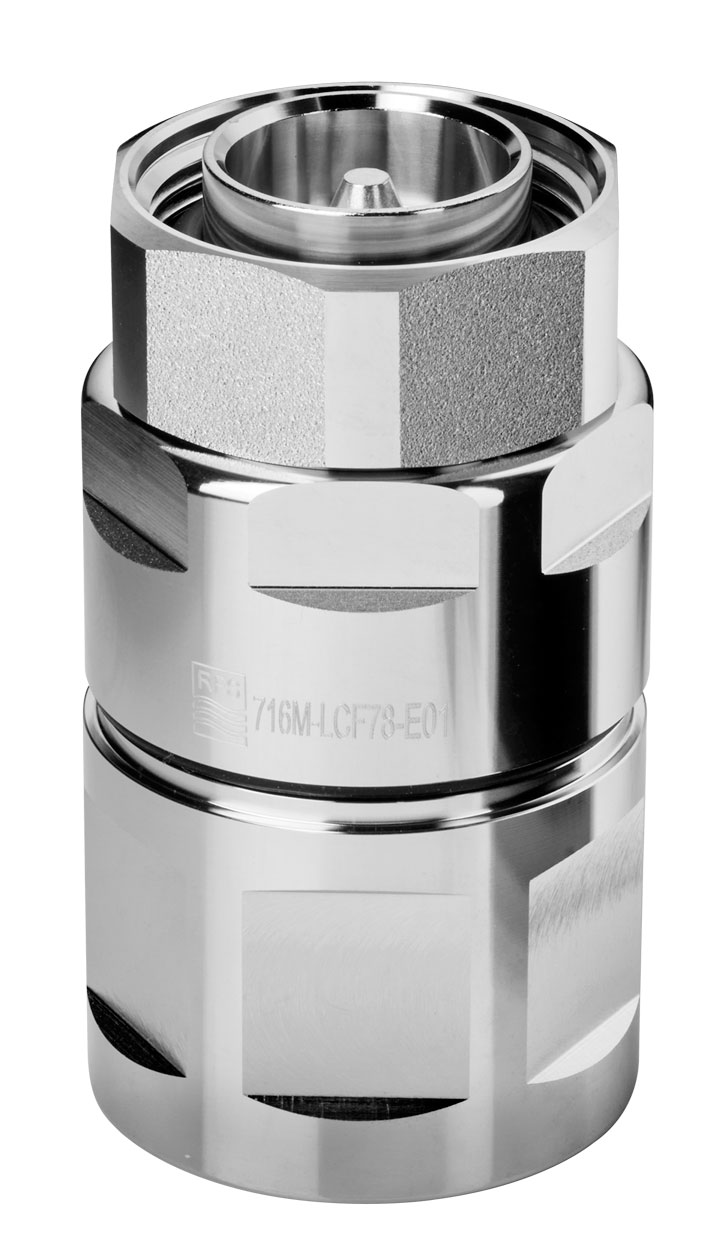
716M-LCF78-E01
7-16 DIN Male Connector for 7/8" Coaxial Cable, OMNI FIT™ Premium,
Straight, O-Ring and compression sealing
- Connector Type :
OMNI FIT™ PREMIUM Straight
- Gender : Male
Grounding Kit
Connector grounding kit
High speed grounding kit for CELLFLEX® LCF 78
Grounding Kit, Pre-formed Copper Strap, 1.5m (60") for CELLFLEX® 7/8" Cable
Wall Feedthrough Sealing
Feed through assemblies for 7/8" coaxial cable, 102mm (4"), 1-entry
Feed through assemblies for 7/8" coaxial cable, 102mm (4"), 2-entries
Feed through assemblies for 7/8" coaxial cable, 102mm (4"), 3-entries
Feed through assemblies for 7/8" coaxial cable, 102mm (4"), 4-entries
Wall feed through (without feed through plate)
Tools
Stripping tool for high speed grounding kit GKSPEED-78 series
Hand tool kit for the installation of connectors and grounding kits on CELLFLEX® Cables
Hoisting Grip for Coaxial Cable and Elliptical Waveguide, Closed Lacing
Hoisting Grip for Coaxial Cable and Elliptical Waveguide, Lace-Up
Automated trimming tool, LCF78, UCF 78, OMNI FIT Premium, Trim Series D01
Flaring Tool LCF 7/8" for Universal Trimming Tools
Clamps
Double Multi-block hanger three layers, with angle member adapter
Double Multi-block hanger one layer, with angle member adapter
Single Multi-block hanger one layer, with angle member adapter
Single Multi-block hanger two layer, with angle member adapter
Single Multi-block hanger three layer, with angle member adapter
Cable hanger, non-insulated, bolt-on, for 7/8" coaxial cable and E100, E105 elliptical waveguide
Snap-In Hangers, 7/8", stainless steel (kit of 10)
Stackable Snap-In Hangers, 7/8", stainless steel (kit of 10)
Connectors
4.3-10 Female Connector for 1/2" Coaxial Cable, OMNI FIT™ standard, O-ring sealing
N Male Connector for 7/8" Coaxial Cable, OMNI FIT™ Premium,
Straight, O-Ring and compression sealing
N Female Connector for 7/8" Coaxial Cable, OMNI FIT™ Premium,
Straight, O-Ring and compression sealing
7-16 DIN Male Connector for 7/8" Coaxial Cable, OMNI FIT™ Premium,
Right Angle, O-Ring and compression sealing
7-16 DIN Male Connector for 7/8" Coaxial Cable, OMNI FIT™ Premium,
Straight, O-Ring and compression sealing
7-16 DIN Female Connector for 7/8" Coaxial Cable, OMNI FIT™ Premium, Straight, O-Ring and compression sealing
4.3-10 Male Straight Connector for 7/8" Coaxial Cable, OMNI FIT™ Premium, Polymer claw and compression sealing
4.3-10 Female Straight Connector for 7/8" Coaxial Cable, OMNI FIT™ Premium, Polymer claw and compression sealing
N Male Connector for 7/8" Coaxial Cable, OMNI FIT™ standard, O-ring sealing
7-16 DIN Female Connector for 7/8" Coaxial Cable, OMNI FIT™ standard, O-ring sealing
N Male Connector for 7/8" Coaxial Cable, OMNI FIT™ standard, O-ring sealing
N Female Connector for 7/8" Coaxial Cable, OMNI FIT™ standard, O-ring sealing
7-16 Male Connector for 7/8" Coaxial Cable, OMNI FIT™ standard, O-ring sealing
7-16 DIN Female Connector for 7/8" Coaxial Cable, OMNI FIT™ standard, O-ring sealing
4.3-10 Male Push-Pull Connector for 7/8" Coaxial Cable, OMNI FIT™ standard, O-ring sealing
4.3-10 Male Connector for 7/8" Coaxial Cable, OMNI FIT™ standard, O-ring sealing
4.3-10 Male Hand-Screw Connector for 7/8" Coaxial Cable, OMNI FIT™ standard, O-ring sealing
4.3-10 Female Connector for 7/8" Coaxial Cable, OMNI FIT™ standard, O-ring sealing
7-16 DIN Female Connector for 7/8" Coaxial Cable, OMNI FIT™ Premium, Straight, O-Ring and compression sealing
4.3-10 Female Straight Connector for 7/8" Coaxial Cable, OMNI FIT™ Premium, O-Ring and compression sealing
4.3-10 Male Straight Connector for 7/8" Coaxial Cable, OMNI FIT™ Premium, O-Ring and compression sealing
N Male Connector for 7/8" Coaxial Cable, OMNI FIT™ Premium,
Straight, O-Ring and 360° compression sealing
N Female Connector for 7/8" Coaxial Cable, OMNI FIT™ Premium,
Straight, O-Ring and 360° compression sealing
Coaxial Transmission Line
7/8" CELLFLEX® Lite Low-Loss Foam-Dielectric Coaxial Cable
7/8" CELLFLEX® Premium Attenuation Low-Loss Foam-Dielectric Coaxial Cable
7/8" CELLFLEX® Lite Low-Loss Foam-Dielectric Coaxial Cable
7/8" CELLFLEX® Premium Attenuation Low-Loss Foam-Dielectric Coaxial Cable
7/8" CELLFLEX® Premium Attenuation Low-Loss Foam-Dielectric Coaxial Cable

716F-LCF78-E01
7-16 DIN Female Connector for 7/8" Coaxial Cable, OMNI FIT™ Premium, Straight, O-Ring and compression sealing
- Connector Type :
OMNI FIT™ PREMIUM Straight
- Gender : Female
Grounding Kit
Connector grounding kit
High speed grounding kit for CELLFLEX® LCF 78
Grounding Kit, Pre-formed Copper Strap, 1.5m (60") for CELLFLEX® 7/8" Cable
Wall Feedthrough Sealing
Feed through assemblies for 7/8" coaxial cable, 102mm (4"), 1-entry
Feed through assemblies for 7/8" coaxial cable, 102mm (4"), 2-entries
Feed through assemblies for 7/8" coaxial cable, 102mm (4"), 3-entries
Feed through assemblies for 7/8" coaxial cable, 102mm (4"), 4-entries
Wall feed through (without feed through plate)
Tools
Stripping tool for high speed grounding kit GKSPEED-78 series
Hand tool kit for the installation of connectors and grounding kits on CELLFLEX® Cables
Hoisting Grip for Coaxial Cable and Elliptical Waveguide, Closed Lacing
Hoisting Grip for Coaxial Cable and Elliptical Waveguide, Lace-Up
Automated trimming tool, LCF78, UCF 78, OMNI FIT Premium, Trim Series D01
Flaring Tool LCF 7/8" for Universal Trimming Tools
Clamps
Double Multi-block hanger three layers, with angle member adapter
Double Multi-block hanger one layer, with angle member adapter
Single Multi-block hanger one layer, with angle member adapter
Single Multi-block hanger two layer, with angle member adapter
Single Multi-block hanger three layer, with angle member adapter
Cable hanger, non-insulated, bolt-on, for 7/8" coaxial cable and E100, E105 elliptical waveguide
Snap-In Hangers, 7/8", stainless steel (kit of 10)
Stackable Snap-In Hangers, 7/8", stainless steel (kit of 10)
Connectors
4.3-10 Female Connector for 1/2" Coaxial Cable, OMNI FIT™ standard, O-ring sealing
N Male Connector for 7/8" Coaxial Cable, OMNI FIT™ Premium,
Straight, O-Ring and compression sealing
N Female Connector for 7/8" Coaxial Cable, OMNI FIT™ Premium,
Straight, O-Ring and compression sealing
7-16 DIN Male Connector for 7/8" Coaxial Cable, OMNI FIT™ Premium,
Right Angle, O-Ring and compression sealing
7-16 DIN Male Connector for 7/8" Coaxial Cable, OMNI FIT™ Premium,
Straight, O-Ring and compression sealing
7-16 DIN Female Connector for 7/8" Coaxial Cable, OMNI FIT™ Premium, Straight, O-Ring and compression sealing
4.3-10 Male Straight Connector for 7/8" Coaxial Cable, OMNI FIT™ Premium, Polymer claw and compression sealing
4.3-10 Female Straight Connector for 7/8" Coaxial Cable, OMNI FIT™ Premium, Polymer claw and compression sealing
N Male Connector for 7/8" Coaxial Cable, OMNI FIT™ standard, O-ring sealing
7-16 DIN Female Connector for 7/8" Coaxial Cable, OMNI FIT™ standard, O-ring sealing
N Male Connector for 7/8" Coaxial Cable, OMNI FIT™ standard, O-ring sealing
N Female Connector for 7/8" Coaxial Cable, OMNI FIT™ standard, O-ring sealing
7-16 Male Connector for 7/8" Coaxial Cable, OMNI FIT™ standard, O-ring sealing
7-16 DIN Female Connector for 7/8" Coaxial Cable, OMNI FIT™ standard, O-ring sealing
4.3-10 Male Push-Pull Connector for 7/8" Coaxial Cable, OMNI FIT™ standard, O-ring sealing
4.3-10 Male Connector for 7/8" Coaxial Cable, OMNI FIT™ standard, O-ring sealing
4.3-10 Male Hand-Screw Connector for 7/8" Coaxial Cable, OMNI FIT™ standard, O-ring sealing
4.3-10 Female Connector for 7/8" Coaxial Cable, OMNI FIT™ standard, O-ring sealing
7-16 DIN Male Connector for 7/8" Coaxial Cable, OMNI FIT™ Premium,
Straight, O-Ring and compression sealing
4.3-10 Female Straight Connector for 7/8" Coaxial Cable, OMNI FIT™ Premium, O-Ring and compression sealing
4.3-10 Male Straight Connector for 7/8" Coaxial Cable, OMNI FIT™ Premium, O-Ring and compression sealing
N Male Connector for 7/8" Coaxial Cable, OMNI FIT™ Premium,
Straight, O-Ring and 360° compression sealing
N Female Connector for 7/8" Coaxial Cable, OMNI FIT™ Premium,
Straight, O-Ring and 360° compression sealing
Coaxial Transmission Line
7/8" CELLFLEX® Lite Low-Loss Foam-Dielectric Coaxial Cable
7/8" CELLFLEX® Premium Attenuation Low-Loss Foam-Dielectric Coaxial Cable
7/8" CELLFLEX® Lite Low-Loss Foam-Dielectric Coaxial Cable
7/8" CELLFLEX® Premium Attenuation Low-Loss Foam-Dielectric Coaxial Cable
7/8" CELLFLEX® Premium Attenuation Low-Loss Foam-Dielectric Coaxial Cable

LCF78-50JA
7/8" CELLFLEX® Premium Attenuation Low-Loss Foam-Dielectric Coaxial Cable
- Applications : Main feed line, intended for outdoor usage
- Jacket Option : Black

43F-LCF78-E01
4.3-10 Female Straight Connector for 7/8" Coaxial Cable, OMNI FIT™ Premium, O-Ring and compression sealing
- Connector Type : OMNI FIT™ PREMIUM Straight
- Gender : Female
Grounding Kit
Connector grounding kit
High speed grounding kit for CELLFLEX® LCF 78
Grounding Kit, Pre-formed Copper Strap, 1.5m (60") for CELLFLEX® 7/8" Cable
Wall Feedthrough Sealing
Feed through assemblies for 7/8" coaxial cable, 102mm (4"), 1-entry
Feed through assemblies for 7/8" coaxial cable, 102mm (4"), 2-entries
Feed through assemblies for 7/8" coaxial cable, 102mm (4"), 3-entries
Feed through assemblies for 7/8" coaxial cable, 102mm (4"), 4-entries
Wall feed through (without feed through plate)
Tools
Stripping tool for high speed grounding kit GKSPEED-78 series
Hand tool kit for the installation of connectors and grounding kits on CELLFLEX® Cables
Hoisting Grip for Coaxial Cable and Elliptical Waveguide, Closed Lacing
Hoisting Grip for Coaxial Cable and Elliptical Waveguide, Lace-Up
Automated trimming tool, LCF78, UCF 78, OMNI FIT Premium, Trim Series D01
Flaring Tool LCF 7/8" for Universal Trimming Tools
Clamps
Double Multi-block hanger three layers, with angle member adapter
Double Multi-block hanger one layer, with angle member adapter
Single Multi-block hanger one layer, with angle member adapter
Single Multi-block hanger two layer, with angle member adapter
Single Multi-block hanger three layer, with angle member adapter
Cable hanger, non-insulated, bolt-on, for 7/8" coaxial cable and E100, E105 elliptical waveguide
Snap-In Hangers, 7/8", stainless steel (kit of 10)
Stackable Snap-In Hangers, 7/8", stainless steel (kit of 10)
Connectors
4.3-10 Female Connector for 1/2" Coaxial Cable, OMNI FIT™ standard, O-ring sealing
N Male Connector for 7/8" Coaxial Cable, OMNI FIT™ Premium,
Straight, O-Ring and compression sealing
N Female Connector for 7/8" Coaxial Cable, OMNI FIT™ Premium,
Straight, O-Ring and compression sealing
7-16 DIN Male Connector for 7/8" Coaxial Cable, OMNI FIT™ Premium,
Right Angle, O-Ring and compression sealing
7-16 DIN Male Connector for 7/8" Coaxial Cable, OMNI FIT™ Premium,
Straight, O-Ring and compression sealing
7-16 DIN Female Connector for 7/8" Coaxial Cable, OMNI FIT™ Premium, Straight, O-Ring and compression sealing
4.3-10 Male Straight Connector for 7/8" Coaxial Cable, OMNI FIT™ Premium, Polymer claw and compression sealing
4.3-10 Female Straight Connector for 7/8" Coaxial Cable, OMNI FIT™ Premium, Polymer claw and compression sealing
N Male Connector for 7/8" Coaxial Cable, OMNI FIT™ standard, O-ring sealing
7-16 DIN Female Connector for 7/8" Coaxial Cable, OMNI FIT™ standard, O-ring sealing
N Male Connector for 7/8" Coaxial Cable, OMNI FIT™ standard, O-ring sealing
N Female Connector for 7/8" Coaxial Cable, OMNI FIT™ standard, O-ring sealing
7-16 Male Connector for 7/8" Coaxial Cable, OMNI FIT™ standard, O-ring sealing
7-16 DIN Female Connector for 7/8" Coaxial Cable, OMNI FIT™ standard, O-ring sealing
4.3-10 Male Push-Pull Connector for 7/8" Coaxial Cable, OMNI FIT™ standard, O-ring sealing
4.3-10 Male Connector for 7/8" Coaxial Cable, OMNI FIT™ standard, O-ring sealing
4.3-10 Male Hand-Screw Connector for 7/8" Coaxial Cable, OMNI FIT™ standard, O-ring sealing
4.3-10 Female Connector for 7/8" Coaxial Cable, OMNI FIT™ standard, O-ring sealing
7-16 DIN Male Connector for 7/8" Coaxial Cable, OMNI FIT™ Premium,
Straight, O-Ring and compression sealing
7-16 DIN Female Connector for 7/8" Coaxial Cable, OMNI FIT™ Premium, Straight, O-Ring and compression sealing
4.3-10 Male Straight Connector for 7/8" Coaxial Cable, OMNI FIT™ Premium, O-Ring and compression sealing
N Male Connector for 7/8" Coaxial Cable, OMNI FIT™ Premium,
Straight, O-Ring and 360° compression sealing
N Female Connector for 7/8" Coaxial Cable, OMNI FIT™ Premium,
Straight, O-Ring and 360° compression sealing
Coaxial Transmission Line
7/8" CELLFLEX® Premium Attenuation Low-Loss Foam-Dielectric Coaxial Cable
7/8" CELLFLEX® Premium Attenuation Low-Loss Foam-Dielectric Coaxial Cable
7/8" CELLFLEX® Premium Attenuation Low-Loss Foam-Dielectric Coaxial Cable

43M-LCF78-E01
4.3-10 Male Straight Connector for 7/8" Coaxial Cable, OMNI FIT™ Premium, O-Ring and compression sealing
- Connector Type : OMNI FIT™ PREMIUM Straight
- Gender : Male
Grounding Kit
Connector grounding kit
High speed grounding kit for CELLFLEX® LCF 78
Grounding Kit, Pre-formed Copper Strap, 1.5m (60") for CELLFLEX® 7/8" Cable
Wall Feedthrough Sealing
Feed through assemblies for 7/8" coaxial cable, 102mm (4"), 1-entry
Feed through assemblies for 7/8" coaxial cable, 102mm (4"), 2-entries
Feed through assemblies for 7/8" coaxial cable, 102mm (4"), 3-entries
Feed through assemblies for 7/8" coaxial cable, 102mm (4"), 4-entries
Wall feed through (without feed through plate)
Tools
Stripping tool for high speed grounding kit GKSPEED-78 series
Hand tool kit for the installation of connectors and grounding kits on CELLFLEX® Cables
Hoisting Grip for Coaxial Cable and Elliptical Waveguide, Closed Lacing
Hoisting Grip for Coaxial Cable and Elliptical Waveguide, Lace-Up
Automated trimming tool, LCF78, UCF 78, OMNI FIT Premium, Trim Series D01
Flaring Tool LCF 7/8" for Universal Trimming Tools
Clamps
Double Multi-block hanger three layers, with angle member adapter
Double Multi-block hanger one layer, with angle member adapter
Single Multi-block hanger one layer, with angle member adapter
Single Multi-block hanger two layer, with angle member adapter
Single Multi-block hanger three layer, with angle member adapter
Cable hanger, non-insulated, bolt-on, for 7/8" coaxial cable and E100, E105 elliptical waveguide
Snap-In Hangers, 7/8", stainless steel (kit of 10)
Stackable Snap-In Hangers, 7/8", stainless steel (kit of 10)
Connectors
4.3-10 Female Connector for 1/2" Coaxial Cable, OMNI FIT™ standard, O-ring sealing
N Male Connector for 7/8" Coaxial Cable, OMNI FIT™ Premium,
Straight, O-Ring and compression sealing
N Female Connector for 7/8" Coaxial Cable, OMNI FIT™ Premium,
Straight, O-Ring and compression sealing
7-16 DIN Male Connector for 7/8" Coaxial Cable, OMNI FIT™ Premium,
Right Angle, O-Ring and compression sealing
7-16 DIN Male Connector for 7/8" Coaxial Cable, OMNI FIT™ Premium,
Straight, O-Ring and compression sealing
7-16 DIN Female Connector for 7/8" Coaxial Cable, OMNI FIT™ Premium, Straight, O-Ring and compression sealing
4.3-10 Male Straight Connector for 7/8" Coaxial Cable, OMNI FIT™ Premium, Polymer claw and compression sealing
4.3-10 Female Straight Connector for 7/8" Coaxial Cable, OMNI FIT™ Premium, Polymer claw and compression sealing
N Male Connector for 7/8" Coaxial Cable, OMNI FIT™ standard, O-ring sealing
7-16 DIN Female Connector for 7/8" Coaxial Cable, OMNI FIT™ standard, O-ring sealing
N Male Connector for 7/8" Coaxial Cable, OMNI FIT™ standard, O-ring sealing
N Female Connector for 7/8" Coaxial Cable, OMNI FIT™ standard, O-ring sealing
7-16 Male Connector for 7/8" Coaxial Cable, OMNI FIT™ standard, O-ring sealing
7-16 DIN Female Connector for 7/8" Coaxial Cable, OMNI FIT™ standard, O-ring sealing
4.3-10 Male Push-Pull Connector for 7/8" Coaxial Cable, OMNI FIT™ standard, O-ring sealing
4.3-10 Male Connector for 7/8" Coaxial Cable, OMNI FIT™ standard, O-ring sealing
4.3-10 Male Hand-Screw Connector for 7/8" Coaxial Cable, OMNI FIT™ standard, O-ring sealing
4.3-10 Female Connector for 7/8" Coaxial Cable, OMNI FIT™ standard, O-ring sealing
7-16 DIN Male Connector for 7/8" Coaxial Cable, OMNI FIT™ Premium,
Straight, O-Ring and compression sealing
7-16 DIN Female Connector for 7/8" Coaxial Cable, OMNI FIT™ Premium, Straight, O-Ring and compression sealing
4.3-10 Female Straight Connector for 7/8" Coaxial Cable, OMNI FIT™ Premium, O-Ring and compression sealing
N Male Connector for 7/8" Coaxial Cable, OMNI FIT™ Premium,
Straight, O-Ring and 360° compression sealing
N Female Connector for 7/8" Coaxial Cable, OMNI FIT™ Premium,
Straight, O-Ring and 360° compression sealing
Coaxial Transmission Line
7/8" CELLFLEX® Premium Attenuation Low-Loss Foam-Dielectric Coaxial Cable
7/8" CELLFLEX® Premium Attenuation Low-Loss Foam-Dielectric Coaxial Cable
7/8" CELLFLEX® Premium Attenuation Low-Loss Foam-Dielectric Coaxial Cable